 Creating an aligned site modifier
|
Mode |
Tool |
Tool set |
|
Aligned
|
Site Modifiers
|
Site Planning |


An aligned modifier defines a surface based on surrounding surfaces and modifiers, matching their elevation. The aligned modifier aligns with certain geometry, including adjacent roadways, hardscapes, massing models, 3D polygons, landscape areas, walls, and planar pad or pad with retaining edge site modifiers. Aligned modifiers can be complex, non-planar closed shapes that can also be modified with vertical profiles, stake objects, and grade objects. They are similar to an aligned hardscape object. See Aligning hardscapes or modifiers with existing geometry for more information.
The modifier can be applied to the existing or proposed site model; the site model is modified when the site model is updated. Draw an aligned modifier with the Site Modifiers tool, or draw a polyline and then select the Create Objects from Shapes command to change it to an aligned modifier (see Creating objects from shapes).
To create an aligned modifier:
Click the tool and mode. Specify the elevation from the Tool bar if desired.
Select the polyline creation mode; see Polyline tool.
Ensure that Snap to Object is selected in the Snapping set on the Status bar.
Click to set the modifier object’s start point.
Click to set the end of the segment and the beginning of the next. Continue drawing segments in this manner until the object is complete, tracing along the edges of valid objects that the modifier should align to; valid alignment objects are highlighted as you draw. The modifier's edge aligns with the adjacent objects.
Return to the start point, or simply double-click to finish creating the object.
Normally, create grade limits around the modifier. The parameters can be edited from the Object Info palette.
Click to show/hide the parameters.Click to show/hide the parameters.
|
Parameter |
Description |
|
Simplification Tolerance |
Enter a positive value to redefine the horizontal distance between the closest parts of two neighboring portions of the modifier. A longer distance simplifies the modifier polygon, reducing the number of source points that modify the site model. A shorter distance increases the number of source points that modify the site model. A value of 0 (zero) does not simplify the modifier. |
|
Modifier Vertex Count |
Displays the number of vertices created by the site modifier to modify the site model |
|
Apply To |
Specifies whether the site modifier applies to the existing or proposed site model |
|
Update Site Model |
Updates the site model with any site model modifications that have occurred. If the update causes the site model contours to fall outside the minimum/maximum elevation range specified in the site model settings, an alert displays, allowing the range to be adjusted. |
|
Configuration |
Indicates the type of modifier object |
|
Show the surface in 3D |
In 3D views, represents the modifier with a 3D mesh. This is convenient when working with a modifier independently of a site model, or when it's helpful to view the site modifier on the surface of the site model in 3D views. Deselect the option to view only the effects of the modifier on the site model. |
|
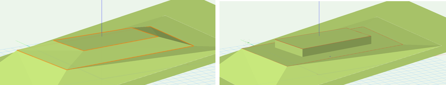
Vertical sides for inner modifiers (closed pad modifiers only) |
Determines whether inner modifiers create a transitional surface (when deselected) or a vertical retaining edge (when selected)
Vertical sides for inner modifiers deselected (on the left) and selected (on the right) |
|
Aligned |
|
|
Realign |
If changes occurred to an adjacent object, resets the affected vertex elevations |
|
Align with Objects on |
Selects the objects to align to, based on location of the objects. This offers flexible control over the alignment. All Layers: Aligns the modifier with geometry from any layer in the file Visible Layers only: Aligns the modifier with modifiers from visible layers only; geometry on invisible layers does not affect the modifier Same Layer as Modifier: Aligns the modifier with geometry that exists only on the same layer Select Layers: Opens the Select Layers dialog box, to choose which layers with geometry can affect the modifier alignment. Click in the Use column to select a layer. To create a new design layer, click New Layer; specify the name for the new layer, and click OK. Custom Set of Layers: Opens the Select Layers dialog box, to select or to modify the selected layers. |
|
Interpolate surface |
Increases the level of detail of the surface created by the profiles and modifiers |
|
Smoothness Sampling |
Enter the sampling rate (0 – 100); higher values add vertices and increase the smoothness of the surface created by the profiles and modifiers |
|
Falloff |
Enter the percentage (0 – 100). This value determines the effect of the surface's defining elements (profiles, stakes, grade objects and adjacent objects) on the interpolated surface. The bigger the value, the less the influence of the defining elements. When the Interpolation Type is Concave, falloff values control the curvature of the surface. Larger falloff values result in a straighter, less curved surface; lower falloff values create a varied curved surface with hills and valleys. When the Interpolation Type is Convex, larger falloff values "pull" more on the surface points. The surface points may move close to the minimum elevation. |
|
Interpolation Type |
Select Concave or Convex, depending on the surface, the falloff value, and the desired results. Concave uses multiquadratic radial function calculations, and usually produces the best results. The surface effects are more stable and minimize the curvature. Convex uses inverse multiquadratic radial function calculations, and is useful when a bigger falloff is desired. The gravitational effect of this option pulls the surface points down to the minimum elevation based on their distance from the defining elements (profiles, stakes, grade objects and adjacent objects). |
|
Elevation |
Specifies the modifier elevation (does not apply to the aligned edges) |
|
Profiles |
|
|
Profile |
Scrolls through the profiles, highlighting the selected one; click the center button to highlight the current profile |
|
Name |
Displays the name of the currently selected profile |
|
Profile Line Class |
Select <Site Modifier Class> to place the profile in the same class as the modifier; select a class, or create a new class, to control profile line appearance and visibility. |
|
Show profile lines |
Toggles the display of all profile line parameters (name, slope, elevation, and markers) |
|
Show profile names |
Toggles the display of all profile names |
|
Show slopes |
Toggles the display of all slope values |
|
Show vertex elevation |
Toggles the display of all vertex elevations |
|
Show profile line markers |
Toggles the display of all profile markers |
|
Add Profile |
Adds a profile line for modifying the surface |
|
Edit Profile |
Enters editing mode for the selected profile, for Editing aligned hardscapes or modifiers with profile lines |
|
Reverse Direction |
Reverses the direction of the profile line section |
|
Profile Line Marker Style |
Opens the Set Marker Style dialog box, to select the profile marker type at each end of the profile line; markers can be the same (Match Beginning) or different (Differentiate) at each end of the section line |
|
Delete Profile |
Deletes the selected profile |
|
Surface Modifiers |
Modifies the surface of the modifier with stake and grade objects |
|
Show Stake Objects |
After modifying the modifier with stake objects, displays the stake objects |
|
Show Grade Objects |
After modifying the modifier with grade objects, displays the grade objects |
|
Edit Surface Modifiers |
Click for Editing aligned hardscapes or modifiers with surface modifiers |
|
Information |
|
|
Update Calculations |
Updates the area and volume calculations displayed in the Object Info palette for the area of the site model located under the site modifier (grade limits must exist around the modifier) |
|
Site model area and volume data |
Displays the area and volume information for the site model area located under the site modifier; select the units for the area and volume (grade limits must exist around the modifier). For more information, see Site model properties. |
|
Vertex parameters |
Edits the path vertices; see Editing vertex-based objects |
|
Move |
Select the vertex, and then edit its X/Y value |
|
Edit |
For vertex selection made in Move, scrolls through the vertices, highlighting the currently selected vertex. Click the center button to highlight the selected vertex. |
To reflect the modification, click Update Site Model from the Object Info palette.
