 Placing distribution amplifiers
|
Tool |
Workspace: Tool set |
|
Distribution Amplifier
|
Design Suite and Spotlight: ConnectCAD Schematics ConnectCAD: Schematics |
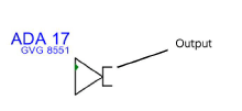
The tool places audio or video distribution amplifiers, which clone an incoming signal to several outputs. They are used where a signal has to go to more than one processing path.
Distribution amplifiers have one input, possibly a loop-thru, and several outputs of the same signal type. Complex distribution amplifiers, like monitoring DA's that perform signal conversions, or stereo audio DA's that have two channels in one device, are considered to be regular devices and are placed with the Device or Device Builder tool.
|
Mode |
Description |
|
Single Click
|
Places a single distribution amplifier at the click location |
|
Linear Array
|
Places an array of distribution amplifiers along the drawn line |
|
Video Distribution Amplifier
|
Inserts a video type of distribution amplifier |
|
Audio Distribution Amplifier
|
Inserts an audio type of distribution amplifier |
|
Make/Model |
Select the make and model from the list |
|
Distribution Amplifier Number |
Select the starting number |
|
Number of Outputs |
Select the number of outputs |
|
Preferences
|
Opens the Distribution Amplifier Preferences dialog box, for specifying default video/audio name prefixes |
To insert a distribution amplifier:
Click the tool, and select either video or audio mode. The available make and models display either video or audio items depending on the mode.
From the Tool bar, select the make and model, starting number, and number of outputs (up to the maximum for the selected model).
If you continue placing the same distribution amplifier, the number automatically increments.
Click to place the distribution amplifier into the drawing. If placing the device into an existing circuit, the device splits the circuit.
In Single Click mode, click once to place the object.

In Linear Array mode, click once to start the array; move the cursor to set the distance and direction of the linear array. Press the Shift key to constrain to the horizontal or vertical direction. The preview indicates the spacing and placement of the objects; the floating Data bar shows the Count. Click to place them.

The device can be edited later from the Object Info palette.
Click to show/hide the parameters.Click to show/hide the parameters.
|
Parameter |
Description |
|
General |
|
|
Device Name |
Displays the device name for use in reports; by default, a device prefix followed by the number displays |
|
Device Type |
Displays the type of device |
|
Symbol |
Displays the symbol selected for the device label; select a different symbol definition from the list if desired. The options include different locations for the tag and description labels. |
|
Display Tag |
Enter the tag name (normally this is the prefix and number of the device) for display on the drawing |
|
Description |
Enter a description, such as the manufacturer and model name, for display on the drawing |
|
Manufacturer |
Enter the make and model for use in reports |
|
Save as Symbol |
Does not apply to distribution amplifiers |
|
Physical |
|
|
Height/Width/Depth |
Enter the dimensions of the device |
|
Power (W) |
Enter the power requirements of the device in watts |
|
Auto BTU calculation |
Automatically converts the power requirements of the device from watts to BTU units (BTU = power in watts x 3.41) |
|
BTU |
To enter power requirements manually, deselect Auto BTU calculation and enter the power requirements of the device in BTU units |
|
Weight (kg) |
Enter the devices's weight in kilograms |
|
Height RU |
Select the height of the device in rack units |
|
Rack Width |
Select whether the width of the device is constrained by the half or the full width of the equipment rack. Select non-rack to use any width, unconstrained by the rack or not placed within a rack. (See the Rack Width description in Placing equipment.) |
|
Configuration |
|
|
Modular |
Indicates that the device is a module that fits in a rack frame |
|
Number of slots |
For modular devices, enter the number of frame slots required in a rack frame |
|
Location |
If an associated equipment item already exists in the layout, displays the device location; otherwise, if you want to assign the device to a layout, enter the location for the corresponding equipment item |
|
Room |
Enter (or displays) the name of the room |
|
Rack |
Enter (or displays) the name of the equipment rack; the rack name displays on the device |
|
Rack U |
Select (or displays) the position of the device in rack units; the value displays on the device |
|
Slot |
Enter (or displays) the slot position, if the device is placed in a rack frame |
|
Opens the DA Settings dialog box. Specify data for the selected device or devices. Make/Model: Select the make and model number from the list. If selecting a make and model with fewer outputs, existing circuit connections may become disassociated. DA Number: Select the device number. Number of Outputs: Select the number of outputs from the device, up to the maximum for the model. Renumber: Renumbers the selection. Select the option, and then select the starting DA Number. |


