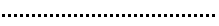
Application window
Each Vectorworks product has a unique workspace that contains the menus, palettes, and tool sets appropriate for that product in a default layout (see Concept: Product workspaces). During a work session, palettes may be opened, closed, and moved around as necessary. When the application is closed, the last workspace settings are preserved and restored for the next session.
To define custom settings for the file that opens each time Vectorworks launches, see Creating templates.
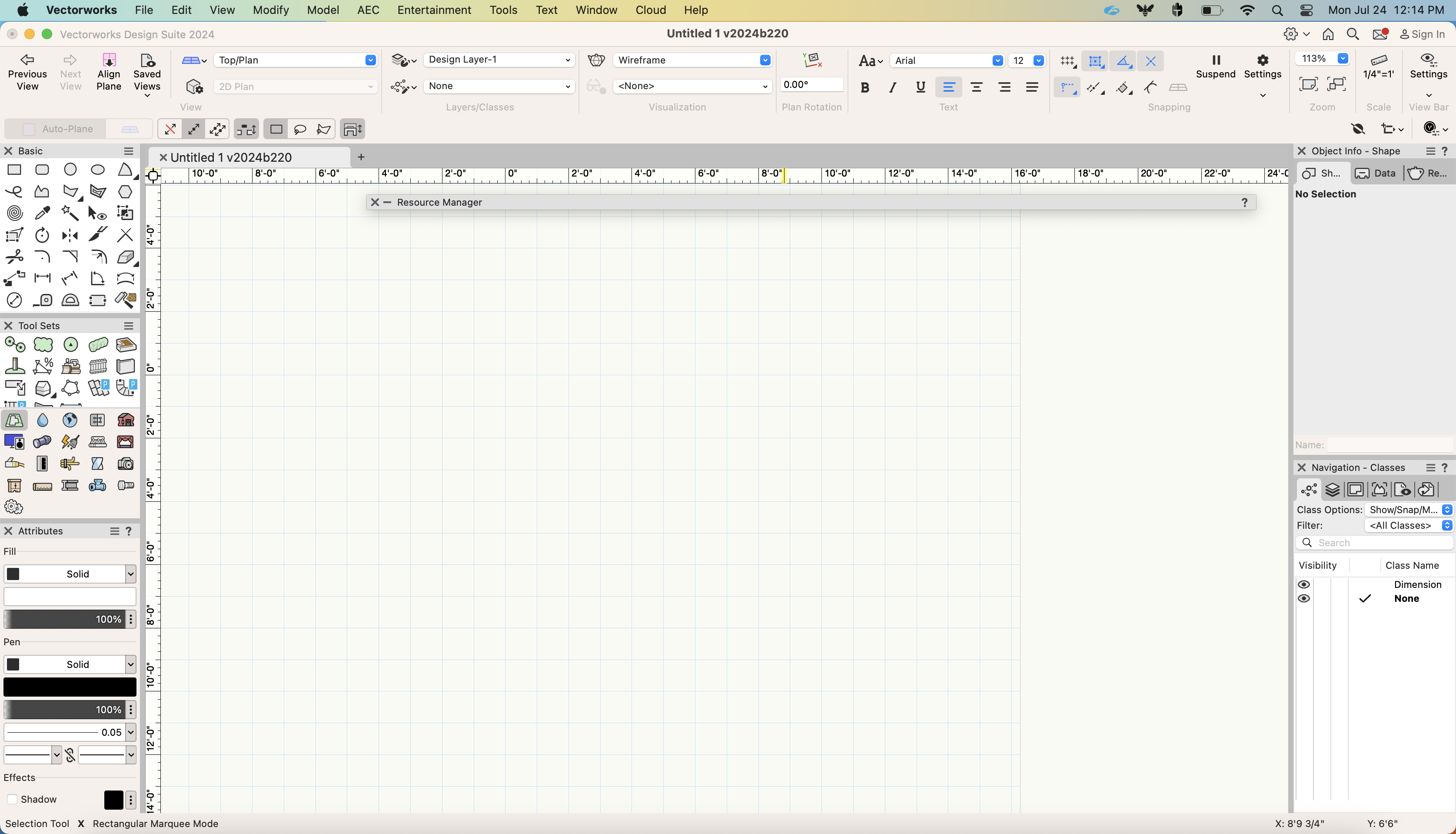
Vectorworks Design Suite workspace on Windows - Light mode
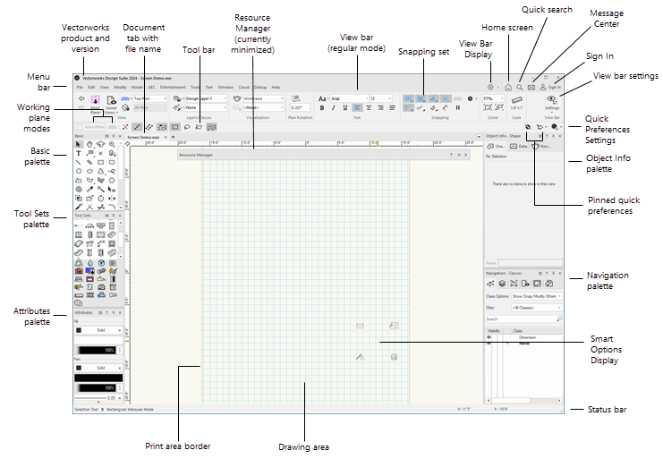
Vectorworks Design Suite workspace on Mac - Light mode
By default, the Vectorworks theme is set to use the operating system's setting for dark or light mode on both Mac and Windows. Vectorworks also uses light background colors for the drawing area and for preview images in dialog boxes by default. These settings can be changed in the General pane of Vectorworks preferences.
You can customize the colors of interface elements as desired, for both light and dark backgrounds. See Interactive appearance settings.
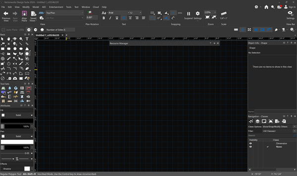
Vectorworks Design Suite workspace on Windows - Dark mode (Use dark background preference enabled)
The View bar and Tool bar use the accent color set for your operating system to indicate certain selected settings, such as quick preferences. You may want to adjust that color for improved visibility.
Windows, palettes, tool sets, and dialog boxes that contain a sizing handle in their bottom right corner can be resized; click-drag the sizing handle to the desired location.
The following table describes some of the workspace features common to all Vectorworks products.
|
Component |
Description |
|
Title bar |
All windows, palettes, tool sets, and dialog boxes have a title bar; click and drag any title bar to move the item to the desired location. See Palette features. |
|
Menu bar |
Contains pull-down menus that access Vectorworks commands; displays controls for the View bar, Home screen, quick search, Message Center, and Vectorworks account sign in |
|
View bar |
Contains buttons and pull-down menus that control the view in various ways; see The View bar |
|
Tool bar |
Displays three types of controls: Working plane modes for 3D drawing are on the far left side; see Working plane modes. Quick preferences are on the far right side; see Setting quick preferences. The various modes that determine the behavior of the active tool are next to the working plane modes. Most tools have multiple modes that may interact when using the tool, and some tools have submodes that are dependent on the activation of specific primary modes. The tool modes are divided into sections grouped by mode function. To move easily through the mode sections from the keyboard, press the U, I, O, P, [ (left bracket), and ] (right bracket) keys. Each key corresponds to a consecutive Tool bar section (see the Mode Modifier shortcuts in Modifying special shortcuts). The tool modes section also accesses the tool preferences and additional essential settings, if any. |
|
Status bar |
Displays informational text, undo messages, minor alerts, and a progress bar (when applicable). The Status bar also displays cursor location fields. When the Snapping set is unpinned from the View bar, it displays on the Status bar. |
|
Data bar |
Depending on the tool and on the action being performed, the floating Data bar displays information such as coordinate data, length, and angle. Use the Data Bar Options quick preference to control how the Data bar functions (see Using the Data bar). These options can also be set from the selections listed under Window > Data Bar Options. |
|
Drawing area |
This is the open portion in the middle of the Vectorworks application window where drawings are created; it includes both the print area and the space that surrounds it |
|
Print area |
Within the drawing area, a gray border defines the print area, if shown. Only the objects that are included within the print area are printed. The print area is divided into pages; each page equals a physical sheet of paper to be printed. A print margin is built in for each page (see The page boundary). |
|
Rulers |
Based on the current measurement system, rulers make it easier to precisely create and place objects within the drawing. The cursor position is highlighted on the rulers, and its appearance can be customized from the Interactive Appearance Settings (see Vectorworks preferences: Interactive pane). The 0,0 point on the rulers represents the location of the user origin, or of the working plane axes when using a working plane. The User Origin command moves the user origin relative to the internal origin, or moves the working plane origin to that of the layer (see Setting the user origin). The rulers can be hidden with an option in the Vectorworks preferences (see Vectorworks preferences: General pane), or from the Quick Preferences menu (see Setting quick preferences). |
|
Grids |
Based on the current measurement system, two grid systems make it easier to precisely create and place objects within the file. To hide the reference grid, deselect Show grid (see Snapping to the grid and Snap and reference grids). |
|
Screen tips |
Screen tips display when the cursor hovers over tools, modes, and certain other palette features. Screen tips identify the item, the keyboard shortcut if there is one, and may contain additional information. |
|
Smart Options Display |
When enabled, Smart Options Display provides context-sensitive access to tools and palettes in the area surrounding the cursor; see Smart Options Display. |