 Drawing walls
|
Tool |
Workspace: Tool set |
Shortcut |
|
Wall
|
Architect and Spotlight: Building Shell Landmark: Building Shell and Site Planning |
9 |

The Wall tool creates hybrid wall objects, simultaneously adding both a 2D and a 3D version of the wall to the drawing; individual walls can be joined into a wall network. Walls can be drawn in Top/Plan or in a 3D view. Straight walls and curved walls, and standard walls and curtain walls, are all created using the same tool.
Create walls by drawing them with the mouse, or by using a mouse-Data bar combination (see Using the Data bar). The following directions assume that the walls are drawn with the mouse.
If walls are drawn using the Data bar, the Control Line mode setting determines whether the dimensions entered are for the left, center, or right edge of the wall, or a custom location.
Polyline mode
|
Mode |
Tool |
Workspace: Tool set |
Shortcut |
|
Polyline
|
Wall
|
Architect and Spotlight: Building Shell Landmark: Building Shell and Site Planning |
9 |

To create walls using Polyline drawing mode:
Click the tool, and then click the appropriate control line modes and drawing mode. (see Creating walls).
Do one of the following:
Click Wall Style from the Tool bar to select a resource from the Resource Selector; see Using wall styles.
Curtain wall styles in the Vectorworks libraries begin with the prefix CW for easy identification.
Click Preferences to open the Wall Preferences dialog box and specify the tool’s default parameters. Depending on the Wall Type, see Standard wall preferences or Curtain wall preferences.
The parameters can be edited later from the Object Info palette.
Click at the starting point of the first wall.
Click again to set the end of the wall and the beginning of the next. Continue drawing walls in this manner until each wall is complete. For more information on the available linear and arc path creation modes, see Creating polylines.
Double-click to finish the last wall if the start point and end point are not at the same location; otherwise, click at the starting location (a SmartCursor cue displays) to connect the walls.
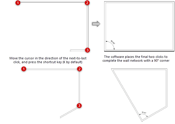
When drawing a wall network, move the cursor in the direction of the next-to-last click but press the shortcut key (K by default) instead of clicking; the software extrapolates the correct alignment and position for a 90° corner and places the final two clicks to complete the wall network.
Corner to Corner mode
|
Mode |
Tool |
Workspace: Tool set |
Shortcut |
|
Corner to Corner
|
Wall
|
Architect and Spotlight: Building Shell Landmark: Building Shell and Site Planning |
9 |

To draw straight walls using using Corner to Corner drawing mode:
Click the tool, and then click the appropriate control line modes and drawing mode (see Creating walls).
Do one of the following:
Click Wall Style from the Tool bar to select a resource from the Resource Selector; see Using wall styles.
Curtain wall styles in the Vectorworks libraries begin with the prefix CW for easy identification.
Click Preferences to open the Wall Preferences dialog box and specify the tool’s default parameters. Depending on the Wall Type, see Standard wall preferences or Curtain wall preferences.
The parameters can be edited later from the Object Info palette.
Click at the wall’s start point; this becomes one corner of the rectangular wall system.
Move the cursor to the opposite corner until the desired size is previewed, and click to set a corner point on the wall system. Four walls are created.
When the Vectorworks preference Auto-join walls is on, walls drawn in Corner to Corner mode that overlap or touch each other interact, so complex wall systems can be drawn quickly. See Automatically joining walls in Corner to Corner mode for the rules that define these interactions.
![]()