Building a device
|
Mode |
Tool |
Workspace: Tool set |
|
Device Builder
|
Device
|
Design Suite, Spotlight: ConnectCAD Schematics ConnectCAD: Schematics |


The Device Builder mode allows you to select and place a standard manufacturer device, or to customize and then place your own device. For more information, see Concept: ConnectCAD devices. The mode is also useful for quickly editing existing devices.
If you create only custom devices, disable the Enable browser option in the Device Preferences dialog box (or deselect the Enable Device Builder device browser option in the ConnectCAD Settings dialog box) so that you do not need to scroll through existing make and model information.
To insert a device with the device builder:
Click the tool, and then click Device Tool Preferences on the Tool bar to open the Device Preferences dialog box and set the tool's default settings. See Device preferences.
Click Device Builder mode.
To place multiple devices along the drawn line, click Linear Array sub-mode (for more information, see Placing a basic device or device symbol).
Optionally, enter a Name and select a Category and/or Make/Model on the Tool bar.
The Device Builder dialog box opens. If you specified a Name and selected a Category and/or Make/Model on the Tool bar, these are already selected.
When the device Name is associated with an existing equipment item, the Make and Model fields and the fields in the physical details group are disabled, and the equipment parameter values are displayed instead.
Enter information about the device and its sockets.
Click to show/hide the parameters.Click to show/hide the parameters.
|
Parameter |
Description |
|
Device Browser |
|
|
Category |
Select the category of device, and click the disclosure arrow to select a device type. Enter text in the search box to filter the list. This selection filters the Make/Model list. Alternatively, select <All> to view all makes and models. |
|
Make/Model |
Select the manufacturer, and click the disclosure arrow to select the model name from the list. The available items shown in the list depend on the selection in Category. Enter text in the search box to filter the list. If the device is already present in the file, this is indicated. If the model, or even the manufacturer, is not available, you can customize the device. To create a custom make and model, select New Make/Model to open the New Make/Model dialog box. Either select a manufacturer, or select New Make. Enter the custom make name, and then specify the model name. Select a Category for the device; in some cases, this determines which tool can place the device later. For example, a category of Distribution Amplifier means that the customized device can be placed with the Distribution Amplifier tool. The new make and model appear in the Make/Model list under your user name for future selection. If Enable browser was not selected in the preferences, the Make and Model are blank so that you can enter custom information. |
|
Delete (trash can) |
Deletes the custom device that is selected from the Make/Model list, removing it from the user folder |
|
Device Identification |
Enter information that appears in labels on the drawing and in worksheets |
|
Device Name |
Enter the name of the device |
|
Display Tag |
Enter the tag name for labels (normally, this is the Device Name) |
|
Display Description |
Enter a description, such as the manufacturer and model name |
|
Label Symbol |
Select a label symbol definition; advanced users can edit the label from the Resource Manager |
|
Enter device physical details |
Because Device Identification parameters define device types, and Enter device physical details parameters are preset to the size of symbol definitions, the parameters cannot be changed. You can edit the parameters after you add a device instance to your drawing. |
|
Device Type |
|
|
Physical |
Creates a device that can automatically create a corresponding equipment item in the layout with the Create Equipment command |
|
Virtual |
Creates a virtual device, with physical dimensions of 0 for the height, width, and depth. A virtual device cannot be associated with equipment items. |
|
Height/Width/Depth |
Enter the device height, width, and depth in millimeters |
|
Height (Rack Units) |
Enter the height in rack units |
|
Rack Width |
Select whether the width of the device is constrained by the half or the full width of the equipment rack. Select non-rack to use any width, unconstrained by the rack or not placed within a rack. |
|
Modular device |
Indicates that the device is modular and is inserted in a rack frame |
|
Module Width (Frame slots) |
For modular devices, enter the number of frame slots required in a rack frame |
|
Power |
Specify the power requirements (the units are set in the ConnectCAD Settings) |
|
Weight |
Enter unit weight (the units are set in the ConnectCAD Settings) |
|
Sockets Definition |
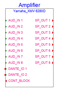
If the manufacturer’s make and model information was recognized by ConnectCAD, the sockets are defined for you. To customize, specify the number of in, out, and IO sockets for each type of signal and connector to be created on the left and right sides of the device. Generally, inputs (and IO) are located on the left, and outputs (and IO) are located on the right. Optionally, specify a Name Prefix. Add +<number> to increment the numbering by a specific value; for example, OUT+3 names the sockets OUT 4, OUT 5, and so on. Sockets are added to the device in row order; the rows can be rearranged by clicking and dragging in the # column. Click in the Use column to include or to exclude the socket. To change, delete, or duplicate multiple sockets at the same time, hold the Shift key while selecting each row. If the number of sockets on the device changes, the device Preview is resized to match the changes. For information about the display order of signals and connectors, editing signals, and editing the connectors and cables associated with a signal, see Specifying ConnectCAD settings. |
|
Add/Delete |
Adds sockets to the device, or deletes the currently selected socket row(s). |
|
Duplicate |
Duplicates the currently selected socket row(s). If desired, you can customize the duplicated row(s) to suit your needs. |
|
Preview |
Displays a preview of the device |
|
Create Temporary Device |
Instead of clicking OK, click this option to create a device that is placed in the drawing, but is not saved as a symbol definition |
Do one of the following:
Click OK to place the device on the drawing and add it as a symbol definition resource in the current file.
Click Create Temporary Device to place a device on the drawing only.