Concept: ConnectCAD devices
Difficulty level: Beginner
Devices are groups of sockets with a label and graphics to depict the device and its function. Connections among devices depict the direction and type of signal flow. Vectorworks comes with thousands of manufacturer’s devices separated into usage categories. You can customize the devices to create your own library of frequently used devices, or create completely custom devices from scratch.
Devices have a schematic appearance, intended for use on schematic drawings, and a layout appearance of the equipment, for 3D modeling and layout views of the drawing.
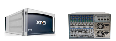
On the left, the schematic device provides a simple diagrammatic view of the connectivity.
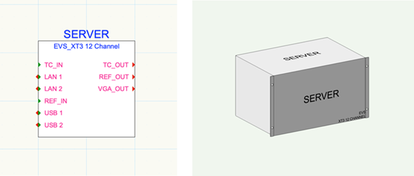
On the right, the equipment item represents the physical model.
The device and the equipment item are associated. The data that defines them (make, model, physical data, location data, and more) is contained in the device definition record, which is part of the equipment item's 3D symbol definition. The information in the record is used to create instances of any given make/model as devices on schematics or layouts. The device definition data can be edited by advanced users; see Editing the device definition data.
Device placement
Place devices on a schematic design layer. If creating devices that are associated with existing symbols on another design layer (such as a floorplan), set both layers to visible. Devices rely on the snap grid for their placement and spacing; ensure that Snap to Grid is enabled. If the devices are not spaced as expected, increase the snap grid distance. See Snapping to the grid for more information.
If you are creating a model view, add the associated 3D versions, the equipment items, on a different, layout design layer. See Creating equipment items automatically.
The Device tool
The Device tool places schematic devices on the drawing. The tool modes function in different ways.
Rectangle mode
Place a generic, simple device with the Device tool in Rectangle mode. After placement, customize the device with sockets and real-world data, and then save it as a symbol definition. As devices are placed and customized (see Editing devices, sockets, and adapters), you can build a library of custom devices that you like to use.
Standard Insertion mode
The Device tool, in Standard Insertion mode, places symbol definitions from the Resource Manager. Alternatively, you can double-click on a symbol from the Resource Manager to activate the Device tool. With an established library of custom device symbol definitions, you can use the Device tool to place a saved device resource, complete with custom graphics and default sockets.
Device Builder mode
Placing manufacturers' devices
In Device Builder mode, the Device tool places a specific device from a manufacturer, complete with the make and model and the proper number of sockets. When you place a device in this way, a symbol definition (named after the make and model) is added to the Resource Manager. When you return to the Device Builder dialog box, symbols that are already in the Resource Manager of the active file are indicated by an (Active Document) prefix, so you can easily see that they're already present in the file.
Temporary devices
If you don’t intend to place the device again and don’t want a symbol definition to be created, you can add it as a temporary device from the Device Builder dialog box. The data for the device instance is derived from the device builder, but the temporary device data is not saved as a symbol in the Resource Manager.
Customizing a manufacturer's device
You can customize a manufacturer's device as you place it with the Device Builder mode, to create a unique instance that is not automatically saved as a symbol definition in the Resource Manager right away. For example, you can select a manufacturer’s device, but remove some of the sockets that come with it by default. After placement, click on an existing device in Device Builder mode to edit the device with the Device Builder dialog box.
Saving temporary and customized instances
If you want to use a temporary or customized device again, or you want to share it, save it as a symbol from the Object Info palette. The device then appears in the Resource Manager.
Other ways of adding devices to the drawing
Convert a custom shape into a basic device with the Modify > Create Objects from Shapes command. Customize the device later by adding sockets and other data.
Create bulk devices from a worksheet with the Create Devices from Worksheet command.
Transfer device properties from one device to another with the eyedropper modes of the Device tool.
Copy and paste devices to create a series of similar devices.
Mirror, or mirror and duplicate, devices across a horizontal or vertical axis line with the Mirror tool. See Mirroring objects across an axis.
Other ways of customizing devices
You can create a completely custom device by creating your own symbol and attaching the device definition record format to its 3D component (see Creating symbol definitions and Attaching record formats to symbols, objects, and materials). To customize the device type, edit the device definition record as described in Editing the device definition data. Device definition records are attached only to the 3D symbol definitions that are physical models of equipment.
For more information, also see Customizing ConnectCAD objects.
You can attach the device definition record format to other types of 3D symbol definitions as well, such as Spotlight objects, so they can be used as a device in ConnectCAD.
To delete a custom device, select it from the Make/Model list in the device builder, and then click Delete (trash can). This prevents temporary or unused devices from cluttering up the Make/Model list.