 Placing a basic device or device symbol
|
Tool |
Workspace: Tool set |
|
Device
|
Design Suite, Spotlight: ConnectCAD Schematics ConnectCAD: Schematics |

The Device tool places a basic device that you can customize, a device symbol definition, or a manufacturer's device. The tool also transfers device properties from one device to another.
|
Mode |
Description |
|
Rectangle
|
Inserts a generic device with no sockets, ready to customize |
|
Standard Insertion
|
Inserts a device from the Device Symbol list of symbol definitions |
|
Device Builder
|
Opens the Device Builder dialog box to select and place a standard manufacturer device, or to customize and then place your own device; see Building a device |
|
Pick Up
|
Copies device characteristics for transfer; see Transferring device properties |
|
Apply
|
Pastes device characteristics |
|
Single Click (Standard Insertion and Device Builder mode)
|
Places a single device at the click location |
|
Linear Array (Standard Insertion and Device Builder mode)
|
Places an array of devices along the drawn line |
|
Name |
Specifies the name of the device; in Device Builder mode, select a Category to enter a default name. If you continue placing devices with the same name, the numeric suffix of the name automatically increments. |
|
Device Symbol (Standard Insertion mode) |
Opens the Resource Selector to select a device resource for placement; double-click a resource to activate it |
|
Category (Device Builder mode) |
Provides a list of device categories. Select the category, and click the disclosure arrow to select a device type. Enter text in the search box to filter the list. This selection filters the Make/Model list. Alternatively, select <All> to view all makes and models. |
|
Make/Model (Device Builder mode) |
Provides a list of manufacturers. Select the manufacturer, and click the disclosure arrow to select the model name from the list. The available items shown in the list depend on the selection in Category. Enter text in the search box to filter the list. If the device is already present in the file, this is indicated. |
|
Device Tool Preferences
|
Opens the Device Preferences dialog box, for setting the tool's default settings; see Device preferences |


To add a device:
Click the tool, and then click Device Tool Preferences on the Tool bar to open the Device Preferences dialog box and set the tool's default settings. See Device preferences.
Do one of the following:
Click Rectangle mode to place a basic, generic device.
Click Standard Insertion mode, and then click Device Symbol on the Tool bar to select a resource from the Resource Selector.
Click Device Builder mode. Select a Category and Make/Model from the Tool bar (alternatively, select these from the Device Builder dialog box).
Open the Resource Manager, open the folder containing the devices saved with the file or in the user folder, and then double-click a device. The tool and Standard Insertion mode are activated, and the Tool bar displays the Device Symbol name.
Optionally, enter the Name of the device.
Place the device. The placement method depends on the selected mode and sub-mode.
In Rectangle mode, click once to set the start point; move the cursor to the opposite corner until the desired size is previewed. Click to insert the device.
In Single Click sub-mode, click once to place the selected symbol instance.
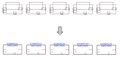
In Linear Array sub-mode, click once to start the array; move the cursor to set the distance and direction of the linear array. Press the Shift key to constrain to the horizontal or vertical direction. The preview indicates the spacing and placement of the objects; the floating Data bar shows the Count. Click to place them.
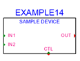
In Standard Insertion mode with a symbol selected, the device can be placed in the drawing on its own or placed into an existing circuit. To be placed into a circuit, the device needs an input on the left and and output on the right, horizontally opposite.
In Device Builder mode, the Device Builder dialog box opens. See Building a device.
As the devices are placed, they are automatically numbered. Sequential autonumbering continues for devices with the same name prefix. Select an existing device, and then select the Device tool, to restart the numbering from that device on.
Device parameters
The device parameters can be edited from the Object Info palette. To complete a basic device, the next step is to add sockets as described in Adding sockets, loops, and terminators.
Click to show/hide the parameters.Click to show/hide the parameters.
|
Parameter |
Description |
|
General |
|
|
Device Name |
Enter the name of the device |
|
Device Type |
Displays the type of device for specialized devices or distribution amplifiers; for regular devices, <generic> displays |
|
Symbol |
Displays the symbol selected for the device label; select a different symbol definition from the list if desired. The options include different locations for the tag and description labels. |
|
Display Tag |
Enter the tag name (normally this is the name of the device) for display on the drawing |
|
Description |
Enter a description, such as the manufacturer and model name, for display on the drawing |
|
Manufacturer |
Enter the make and model for use in reports |
|
Save as Symbol |
Saves the device (and its sockets) as a symbol definition that can be placed on the drawing with Standard Insertion mode. By default, the new symbol is saved with the Make and Model from the Object Info palette, but you can enter a different name. A default 3D symbol definition is automatically created based on the Physical dimensions from the Object Info palette. If the same symbol definition already exists, the symbol is not saved again. |
|
Physical |
|
|
Height/Width/Depth |
Enter the dimensions of the device. Devices with dimensions of 0 are considered virtual devices, which cannot be associated with equipment items. |
|
Power (W) |
Enter the power requirements of the device in watts |
|
Auto BTU calculation |
Automatically converts the power requirements of the device from watts to BTU units (BTU = power in watts x 3.41) |
|
BTU |
To enter power requirements manually, deselect Auto BTU calculation and enter the power requirements of the device in BTU units |
|
Weight (kg) |
Enter the device’s weight in kilograms |
|
Height RU |
Select the height of the device in rack units |
|
Rack Width |
Select whether the width of the device is constrained by the half or the full width of the equipment rack. Select non-rack to use any width, unconstrained by the rack or not placed within a rack. |
|
Configuration |
|
|
Modular |
Indicates that the device is a module that fits in a rack frame |
|
Number of slots |
For modular devices, enter the number of frame slots required in a rack frame |
|
Location |
If an associated equipment item already exists in the layout, displays the device location; otherwise, if you want to assign the device to a layout, enter the location for the corresponding equipment item |
|
Room |
Enter (or displays) the name of the room. If this value matches the Room ID of a layout room, the device is assigned to the layout room. Any equipment item associated with the device will be located in the layout room. Similarly, if the value matches the Name from the Data tab of the Object Info palette of a space object, an associated equipment item is located within the space. (See Creating equipment items automatically and Creating spaces with the Space tool.) |
|
Rack |
Enter (or displays) the name of the equipment rack; the rack name displays on the device |
|
Rack U |
Select (or displays) the position of the device in rack units; the value displays on the device |
|
Slot |
Enter (or displays) the slot position, if the device is placed in a rack frame |
|
Edit Device Array |
This functionality is not available for this type of device |
|
Show Equipment |
Navigates to the equipment item or rack frame that the device is linked to, when it is associated. (See Placing equipment and Placing a rack frame.) |
Selecting devices with the same make and model
If multiple devices on your drawing have the same make and model, you can select all the devices at once.
To select devices with the same make and model:
Right-click on a device.
Select Select Same Make and Model from the context menu.
The devices with the same make and model are selected.
Locating device symbol definitions in the Resource Manager
If a device instance was created from a device symbol definition in the Resource Manager, you can use the Locate Device in Resource Manager context menu command to locate the resource. See Locating a resource from the drawing.
![]()