 Workflow: Creating hanging hardware symbol definitions
Difficulty level: Advanced
If you are an advanced user, and the hanging hardware symbol you need is not available, use this workflow to create a custom symbol definition. The workflow describes how to create the hanging hardware's 3D geometry, define the symbol's default position, and attach the record data needed for hanging hardware functionality.
Hanging hardware refers to clamps for lighting devices, pipe clamps, and sliding tees. The terms "hanging hardware" and "clamp" are used interchangeably throughout the topic.
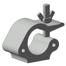
The process of creating the hanging hardware symbol is similar to creating a standalone lighting device, so this workflow makes frequent reference to Workflow: Creating lighting device symbol definitions.
There are a few items to note before getting started. Hanging hardware symbol definitions that are inserted with lighting devices are usually selected from the Tool bar when inserting the lighting device. Clamps attach to the base of the lighting device; however, if the lighting device doesn't contain a base part it attaches to the yoke. To make a clamp behave like part of the lighting device base, you will define clamps as a Base part in the Parts record.
As an alternative to creating a hanging hardware symbol from scratch, use the hanging hardware symbols in the Vectorworks libraries. Check the available content to see if you can adapt it to meet your needs. Navigate to Libraries\Entertainment\Rigging\Hardware_Hanging to find the hanging hardware symbol definitions. Copy the relevant .vwx folder to your user folder in the appropriate location, and then open the desired .vwx file. If you decide to use the hanging hardware symbols instead of creating your own, you can skip the steps in Drawing the hanging hardware's 3D geometry and proceed to Creating the hanging hardware's 3D symbol definition.
Drawing the hanging hardware's 3D geometry
To draw the hanging hardware's 3D geometry:
The geometry should be simple and accurately sized. Too many details can take a long time to render.
To reduce file size, the 3D components should consist of 3D solids. Avoid using meshes or NURBS objects. Instead, use extrudes, sweeps, additions, subtractions, and so on. If you perform multiple operations to shape a component, convert it to a generic solid when completed. See Concept: 3D modeling for more information about 3D modeling tools and commands.
Set the fill color to Cool Gray 90% for all components (this color is available from the Standard Vectorworks Colors palette).
Apply the default texture to all components. From the Resource Manager, search for "Default Instrument Texture" to locate the black, white, and silver options.
Most lighting devices do not include a clamp, so your custom clamp will be inserted as hanging hardware when inserting a light with the Lighting Device tool. If the selected lighting device already contains a default clamp, which is rare, the clamp must be removed before you can select your custom clamp. Remove the hanging hardware geometry and the 3D locus, and then move the insertion point of the lighting device up at 0,0 and the desired Z height.
A 3D locus must be placed at the bottom of the clamp where it connects to the light for rotation; place the locus in the Lighting-Clamps-NonPlot class for proper functionality.
For ground level lighting devices with feet, if a clamp is selected upon insertion of a lighting device, the clamp is attached to the body of the device, just below the feet.
For some lighting devices that require two clamps, create a clamp symbol that contains two clamps within one symbol. Place a single 3D locus at an equal distance between both clamps with an insertion point at 0,0 and the desired Z height.
Creating the hanging hardware's 3D symbol definition
To create the 3D symbol:
Follow the steps described in Creating the 3D symbol definition. By default, the insertion point of the hanging hardware is located at the center of where it connects to the lighting device, pipe, or truss, which is the center of the geometry in Top/Plan view.
Attaching the Parts record to the hanging hardware
The Parts record assigns the clamp to the base of the lighting device. Clamps are considered to be Base parts. When a clamp is attached, the lighting symbol moves so the device hangs correctly; however, the insertion point does not change. Attaching a clamp that has a special offset also does not change the insertion point of the lighting device. For those instances, the lighting symbol's pan and tilt is determined by their rotation center instead of the insertion point.
To attach the Parts record:
From the Resource Manager, locate the Parts record from one of the lighting device library files included with the Spotlight program, and drag it to the active file. Alternatively, right-click on the record, and select Import from the context menu.
Select the new clamp symbol, and select Modify > Edit Symbol.
Click the Data tab on the Object Info palette. Click Attach Record to open the Resource Selector, and double-click the Parts record to attach it.
Select the Base part for the clamp.
Click Exit Symbol at the upper right corner of the window to return to the drawing.
Attaching the Light Info Record and EntEquipUniversal record
These two records specify the default clamp values and they are required for your hanging hardware symbol to function properly.
To attach the required record formats:
From the Resource Manager, locate the Light Info Record and the EntEquipUniversal record from one of the lighting device library files included with the Spotlight program, and drag them to the active file. Alternatively, right-click on the records, and select Import from the context menu.
Select the new clamp symbol and select Modify > Edit Symbol.
In the Edit Symbol window, click an empty location so that nothing is selected.
Click the Data tab on the Object Info palette. Click Attach Record to open the Resource Selector, and double-click the Light Info Record to attach it to the symbol.
Specify the Device Type in the Light Info Record, as Clamp for clamps that attach to lighting devices, Pipe Clamp for hanging hardware for pipes, or Hanging Hardware for sliding tees.
Similarly, attach the EntEquipUniversal record and enter its record information.
The Device Type is Clamp for clamps, Rigging for pipe clamps, or Sliding Tee for sliding tees. The Short name field parameter can be set to a custom name. Use a name that works for your reports.
Click Exit Symbol at the upper right corner of the window to return to the drawing.
Information from the Light Info and additional records attached to the hanging hardware symbol applies to the lighting device's hanging hardware-specific parameters. These parameters are indicated in the Accessory column of the parameter list on the Spotlight preferences: Lighting Devices: Parameters pane.
