 Adding a survey point
|
Tool |
Workspace: Tool set |
|
Survey Point
|
Design Suite, Architect, Landmark: GIS Spotlight: Event |

|
Command |
Path |
|
Geolocation |
File > Document Settings |
Choosing the Coordinate Reference System (CRS) is one part of georeferencing the file; the other portion is adding a survey point. The survey point indicates the location of a known point, and optionally, two reference points, and allows you to define how the geometry should relate to the georeferencing coordinates. A survey point is a project's reference point, and it doesn't have to align with the internal origin.
A survey point can be inserted at the beginning of a project, in an empty file, which is the preferred method. Alternatively, insert the survey point into an already georeferenced project or add it automatically when importing a georeferenced file. A file can contain only one survey point.
A survey point is inserted by one of three methods:
Click the tool. The Geolocation Setup Wizard guides you to place the survey point in the optimal location for your situation.
Select the Geolocation command. Select the CRS and other parameters as described in Specifying georeferencing and geolocation. Then click Create Survey Point.
Import a file with georeferencing.
Inserting a survey point with the geolocation wizard
To insert a survey point with the geolocation wizard:
Click the tool.
The Geolocation Setup Wizard opens.
The wizard walks you through your project's situation, helping you choose a CRS and place the survey point appropriately.
The wizard can remain open while you work. You can specify the appearance of the survey point by clicking Preferences from the Tool bar, or from the Object Info palette after placement.
Inserting a survey point manually
To insert a survey point manually:
Select the Geolocation command.
The Geolocation dialog box opens.
Set the georeferencing coordinate system as described in Specifying georeferencing and geolocation.
Click Create Survey Point.
Click in the drawing to place the survey point.
Survey point settings
Whether you place the survey point by the wizard or with the Geolocation dialog box, or by importing a file, you need to specify the survey point settings at some point. These parameters specify the coordinates of the survey point and the angle from True North. If you are including reference points for triangulation, set the coordinates for each one (these must be specified, since they cannot be picked up from the drawing automatically).
The Survey Point Setup dialog box opens.
Click to show/hide the parameters.Click to show/hide the parameters.
|
Parameter |
Description |
|
Coordinate Reference System (CRS) |
|
|
EPSG |
Displays the EPSG code of the currently selected coordinate system; click the link for more information online |
|
CRS Name |
Displays the name of the currently selected coordinate system |
|
Units |
Displays the units of the currently selected coordinate system |
|
Edit |
Selects a different coordinate system. See Specifying georeferencing and geolocation. |
|
Coordinates and Angle |
Specify the geographical point represented by the survey point by choosing one of the coordinate methods |
|
Geographical (WGS-84) coordinates |
Select this option and enter the WGS-84 latitude/longitude coordinates. The WGS-84 coodinates remain the same, regardless of the selected CRS. |
|
Cartesian coordinates |
Select this option and enter Easting and Northing coordinates. Cartesian coordinates are dependent on the starting location of the CRS's Cartesian grid. The latitude/longitude and Cartesian coordinates are aligned; if you change one, the other is adjusted accordingly. |
|
Use X/Y coordinates from user origin grid |
Uses the coordinates from the user origin (as displayed by the rulers in the drawing area) as the survey point coordinates, instead of the Easting/Northing coordinates |
|
Angle from True North |
Specify the angle from true north if you prefer to work in Project North; this indicates the difference between Project North and true north. Use an azimuth degree measurement (0° is along the Y axis, 90° is along the positive X axis). This rotates the geographical coordinate grid through the survey point (rather than through the internal origin). The survey point is always rotated to indicate true North. If you’re working in, and sharing a file that is set up in, Project North, it’s important to specify the angle from true north. This allows the receiver to adjust the file to its surrounding site. By setting up georeferencing in the background with the correct angle from true north, you can still work in Project North while providing context for the project. You can use the basemap in the background for the project, but also easily export the file to IFC in True North rotation. The Geographic Transformation Mode dialog box opens. See Editing the survey point and transforming existing geometry. |
|
Internal and User Origins |
Specify whether to align the survey point and the internal origin and/or user origin |
|
Align the survey point with the internal origin |
Aligns the survey point with the location of the the internal origin; you can also click on the internal origin while placing the stake to align them. If you have already centered the drawing on the internal origin, this option is automatically selected. Display a marker for the internal origin from the Display pane of the Vectorworks preferences. |
|
Align the user origin grid (X/Y) with the geographical coordinates (E/N) |
Aligns the user origin with the georeference grid, so that X, Y coordinates of the user origin match the Easting and Northing coordinates. Deselect the option if you prefer to use the user origin as a base point or specify different X, Y coordinates. If Use X/Y coordinates from user origin grid was selected, this option is also automatically selected. If an Angle from True North was specified, only the survey point will have the correct X/Y coordinates, since the user origin grid (X/Y) cannot be rotated. |
|
Reference Points |
|
|
Set triangulation reference points |
Adds two triangulation reference points in addition to the survey point; these reference points use the same coordinate system that was selected for the survey point |
|
Point A / Point B |
Specify the coordinates for the reference points; also, provide a Name for each point |
|
Object Info palette only |
These parameters affect the display of information on the survey point label. Only the parameters that are different on the Object Info palette are described here. |
|
Survey Point Settings |
Click Survey Point Settings from the Object Info palette to make changes. Normally, the survey point never moves; only change the parameters if you have made an error when specifying the coordinates or angle. This will adjust the map to the selected coordinates. You will need to either edit the CRS, or confirm that you want to keep it as is. The Survey Point Settings dialog box opens. Once changes are made, the survey point is locked again. The point remains in the same location in the drawing; what has changed is the georeferencing that it represents. If you changed the CRS, specify the transformation mode for existing objects as described below. |
|
Graphics |
|
|
Survey Point/ Reference Points |
Click the survey point and reference point selector to select a resource for each from the Resource Selectors |
|
Text Style/ Font Name / Font Size |
Specify the font and properties for the survey point labels |
|
2D Scale Factor/ 3D Scale Factor |
Set the survey point scale factor for Top/Plan and 3D views |
|
Coordinates |
|
|
Primary Coordinates |
Select the format for the primary coordinates |
|
Secondary Coordinates |
Select the format for the secondary coordinates, or choose None to hide them |
|
Decimal Precision |
Specify the precision to use for the coordinate labels |
|
Show angle from true north |
Displays the angle next to the survey point |
|
Use project elevation |
Displays the project elevation |
Click to place the survey point and, optionally, the reference points for triangulation.
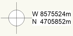
Once the survey point has been placed, it cannot be moved; it is locked to its geographical coordinates. Georeferencing changes are not permitted from the Geolocation dialog box.
If the distance between the survey point and the internal origin is too large, an alert opens, informing you that the survey point and nearby geometry will be centered about the internal origin.
The internal origin cannot be moved. However, the user origin can be freely moved, so you can switch between using the user origin for displaying Northing/Easting and using it as a project grid. Deselect the option to Align the user origin (X,Y) with the geographical coordinates.
If you delete the survey point, the file is no longer geolocated. You can place a new one by one of the methods above.
Editing the survey point and transforming existing geometry
|
Mode |
Tool |
Workspace: Tool set |
|
Locate Survey Point
|
Survey Point
|
Design Suite, Architect, Landmark: GIS Spotlight: Event |

The survey point is locked to the specific CRS. If you made an error with the CRS, you can make a change from the Object Info palette of the survey point. You can also specify a different rotation angle from true north. You will need to specify the action to take, if any, to transform exisiting geometry so that it is still correct for the new CRS.
To edit the survey point:
With the Survey Point tool selected, click Locate Survey Point mode to select the survey point.
Alternatively, you can select the point from the Geolocation dialog box. Select File > Document Settings > Geolocation, and click Locate the Survey Point.
Click Survey Point Settings from the Object Info palette.
The Survey Point Setup dialog box opens.
Do one of the following:
If you need to change the CRS, click Edit. Follow the instructions in Specifying georeferencing and geolocation.
If you need to make other changes, such as change the Angle from True North, click Confirm. Make the desired changes.
If your changes require it, the Geographic Transformation Mode dialog box opens. Specify the action to take for any existing objects.
Click to show/hide the parameters.Click to show/hide the parameters.
|
Parameter |
Description |
|
Transformation mode |
Select the appropriate option for transforming the geometry of objects on the selected layer or layers: Do not transform the objects: Objects are not transformed (only the map is moved or transformed); the objects do not move, and they remain in their relative position to the survey point. This option is best for new files without any objects or for objects that do not represent geographical items. Transform/rotate all objects as a group: Best for projecting non-geographic drawing objects, such as architectural plans; this option moves and rotates all objects, but does not change their shape. Transform all objects individually: Best for projecting geographic data, such as municipal boundaries, roads, rivers, and locations on a map; this option moves and scales all objects. If you have made any coordinate changes, select this option. |
|
Transform images to match the coordinate system |
For imported georeferenced images, ensures that the image pixels are at the correct latitude and longitude to match the coordinate system changes |
|
Select the layers to transform/rotate |
Keep the check mark next to the design layers with geometry or existing objects to transform |
