 Concept: GIS and georeferencing
Difficulty level: Intermediate
In the Vectorworks Design Suite products, the geographic information system (GIS) features link your Vectorworks file to a real location on Earth using a defined coordinate system, so distances, shapes, and positions are accurate.
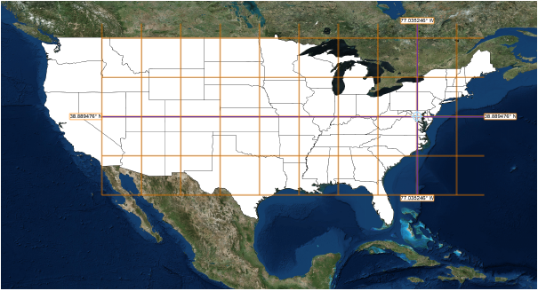
Georeferencing is a system that assigns coordinates to the entire Earth, expressed in latitude and longitude. It allows you to work with geographically aware data. For a small-scale architectural or landscape project, you might need to accurately import information related to the project site, such as property boundaries or municipal utility resources. For a larger scale planning project, you might import multiple shapefiles and image files and arrange them into maps, adding colors, symbols, and notes based on database information. You might then export files for use in other GIS software.
There are two important concepts to understand when using Vectorworks with GIS.
Internal Origin: This is a fixed point in the file. You cannot move it; you only change which real‑world coordinates it represents. It can represent coordinates from georeferencing. Your project should be located close to the internal origin.
User Origin: This is a movable grid used by the rulers. You can place its 0,0 origin anywhere (for example at a building corner) for convenient project coordinates. It cannot be rotated; it remains aligned with the screen. It is independent of georeferencing, though you can align it with georeferenced coordinates if needed. In a new file, the user origin 0,0 is aligned with the internal origin. A non-georeferenced file relies on the user origin grid to define a location. If the file is not georeferenced, the user origin can equal the Easting/Northing grid.
To use GIS features, the file must be both georeferenced and geolocated. Georeferencing the file means that all layers in the file are also georeferenced. (This is a departure from versions of Vectorworks prior to 2027, when individual layers could be georeferenced or not.) Geolocating means that a survey point has been placed.
Georeferencing requires selecting a Coordinate Reference System (CRS) that converts the round Earth to a flat map. The CRS is usually identified by an EPSG code. It defines how latitude/longitude are turned into Easting/Northing in meters or feet. Different regions use different CRSs to reduce distortion. If you use the wrong CRS, measured distances and shapes on the map will be incorrect.
After choosing a CRS, you must geolocate the file; this means placing your project’s coordinates near the internal origin so the model sits at the correct spot on Earth, representing a known location in the world. When you geolocate the file, you spin the globe so that the ‘real-world’ place you’re working at is positioned under the internal origin. This is done by placing a survey point in the drawing and specifying the coordinates that the point represents. To place a survey point, use the Geolocation Setup Wizard, select the Geolocation command, or import a file with georeferencing information.
When placing a survey point, it's assigned real‑world coordinates, and Vectorworks aligns the Earth map to that point. If the survey point is too far away from the internal origin, Vectorworks moves it to the internal origin, and the map follows along. If the survey point is moved, Vectorworks still retains its coordinates.
You can also "tilt" the globe's representation if you need to work in a direction other than true north.
Once you have placed the survey point, it can't be moved. Your project is tied to its true location, and the survey point is associated with the specificed CRS. A file can only have one survey point, with one active CRS, at a time. You can still move the user origin for local project coordinates without changing the geolocation, since the user origin is a completely arbitrary grid.
The Geolocation Setup Wizard
The easiest way to georeference and geolocate the file is with the Geolocation Setup Wizard. Click the Survey Point tool to access the wizard. The wizard provides all of the information you need, and assists you with the proper selections based on your situation, to both georeference and geolocate your project.
The wizard opens every time you select the Survey Point tool. After you've geolocated the file, it will give you other alternatives of what to do, such as rotating the map and geometry to project north, moving the survey point, or deleting it and deleting the CRS for the file.
Other GIS features
You can view the drawing against the proper portion of a basemap image of the area, and align and orient the drawing to that area. (You can do this even without a survey point.) The basemap is a live map that displays on all design layers; it can be toggled on and off easily from the Quick Preferences. Raster image content is loaded from a selected online portal or service, such as WMS servers, Google maps (subscription or Vectorworks Service Select benefits required), or ArcGIS servers under license from Esri (internet access required). The ability to access online services means that a wide variety of content is available, including satellite images, street maps, topographical maps, and much more. Both publicly-available and licensed resources (login required for some services) are available directly from the Vectorworks drawing.
You can also add a geoimage object to a design layer, which displays as a static map overlay on its design layer. It can also be included in sheet layer viewports.
Vectorworks can transform imported geometry from one CRS to another so it matches the CRS set in your file. (Non‑georeferenced files do not get this transformation.) Additional features to make common GIS operations easier include tools for adding GIS-aware stakes, a graticule, and great circle to a drawing.
Vectorworks Architect and Landmark products have access to the full suite of georeferencing tools and commands; the Spotlight product has access to a more limited set of tools and commands.
