 Workflow: Importing georeferenced site files
Difficulty level: Advanced
Collaboration with surveyors and other designers often requires importing one or more DXF/DWG files from other applications.
Configuring the import settings properly helps to:
Georeference and geolocate the imported site data.
Establish both the drawing and the imported data in the correct location.
Avoid precision errors by establishing the Vectorworks internal origin and the user origin location.
Ensure the smooth exchange of a properly set up file if you export the drawing to colleagues later.
This procedure describes importing files from other applications. Referenced layers and design layer viewports from other Vectorworks files are automatically projected to match the georeference settings of the master file.
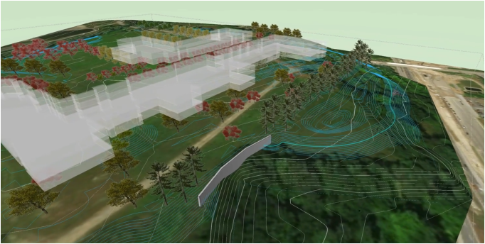
To import site information from one or more files created in another application:
Obtain any needed information from the surveyor or file originator, such as the project location or address; the name, EPSG, or WKT of the coordinate system; and the units.
Create a new file by selecting File > New. Depending on the needs of your organization, create a blank file or use a predefined template.
Do one of the following to place a survey point:
See Adding a survey point for more information.
Click the Survey Point tool. The Geolocation Setup Wizard opens. Select the option to begin with a new file. Specify the exact location of the project and align it with the file’s internal origin. Once the correct location has been found, click Activate Survey Point Tool and click in the drawing to place the survey point and geolocate the file.
If you are familiar with the process, set the coordinate system by selecting File > Document Settings > Geolocation. See Specifying georeferencing and geolocation. In most situations, click Select CRS and choose the appropriate coordinate system by using the EPSG/CRS lookup table. Once the correct CRS has been found, click Create Survey Point to place the survey point and geolocate the file.
If you enabled it, the basemap displays in the background; toggle the display from the Quick Preferences.
You can also place a geoimage object by clicking the Geoimage tool. Following the instructions in Adding a geolocated image, add an image of the site to the project. Update the geoimage from the Object Info palette to download the image again, after saving or closing and reopening the file.
The geoimage can be selected later as a 3D display texture for the site model that you create from the imported data.
Import the DXF/DWG file by selecting File > Import > Import Single DXF/DWG. The import parameters are described in DXF/DWG and DWF import options. In particular, make the following selections:
In Model Space Units, verify the detected units. If necessary, select Import DXF/DWG files using specified units and choose the correct unit.
In Georeferencing and Location, Vectorworks detects that the current file is already geolocated. Align with georeference coordinates is automatically selected.
Click Advanced. On the Conversion pane, verify the automatically detected scale. Leaving the detected scale is recommended; normally, it will center and size the drawing properly on the page. If extraneous objects are located far from the main area in the imported drawing, you may need to adjust the scale.
On the Classes/Layers pane, optionally select Add Prefix to Imported DXF/DWG Layers and enter a prefix to easily identify and organize the imported layers.
The geometry imports at the correct location, matching that of the geoimage.
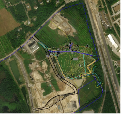
If creating a site model from the imported data, select the imported contour lines. Convert them to 3D polygons by selecting Modify > Convert > Convert to 3D Polys, and simplify the polygons if they have too many vertices (Simplifying 3D polygons). Create the site model as described in Creating the site model.
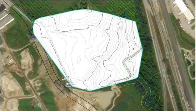
Additional georeferenced DXF/DWG files from the project can now be imported. Align with georeference coordinates is selected.
After completing work on the site plan, you can export the file back to colleagues by selecting File > Export > Export DXF/DWG. Selecting Export layers as separate files is recommended. Verify that the file was properly exported by importing one of the exported files back into Vectorworks, and confirming that it aligns properly with the project location.
