The irrigation tools and commands in the Vectorworks Landmark product allow landscaping professionals to design and analyze irrigation systems, as well as prepare accurate as-built drawings. With various possible workflows, the irrigation suite is useful for irrigation professionals, designers, and consultants, as well as for landscape architects or other designers. System analysis considers and calculates parameters like water pressure, flow rate, and velocity through the system components, while considering how the components interact as part of the entire system. The irrigation system can be sent to the surface of a site model, conforming the elevation of the irrigation network to the terrain.
Because the parameters of the irrigation objects are based on actual manufacturer’s data, irrigation components calculate and report real-world parameter values. However, you are not limited to using manufacturer’s catalogs. The flexibility to create custom irrigation components, as well as specify tolerances for variation or customize manufacturer’s data, means that you can configure the irrigation system as needed.
To assist with the crucial aspect of obtaining the correct size of irrigation pipes and valves, pipes can be automatically sized at placement, and the size of pipes, valves, and system components can be fine-tuned as a whole, ensuring that the optimal irrigation components for the system are included in the design. Warning messages help identify irrigation components that are not achieving required product specifications or are disconnected from the network.
As a starting point for irrigation design, or for generalized irrigation planning, the Hydrozone tool draws a general planting area associated with a specified water requirement and an irrigation method, without requiring the detailed components of an irrigation system. The hydrozone enables designers to evaluate whether the planting design results in efficient use of water, and in some districts, helps ensure that the design complies with water use regulations.
In conjunction with the Vectorworks Landmark’s site model (terrain) suite of tools and commands and other features, irrigation professionals can use the Irrigation tool set and commands to create, analyze, report, and document complete irrigation designs.
● Collaborate with a site design professional colleague and import Site Model Source Data, or use your own site data for Creating the Site Model.
● Analyze the size, shape, climate, soil type and condition, primary usage, water supply and budget, and any special considerations for the site.
● Determine the types of plant material to add to the site and the water requirements. Use the Hydrozone tool to establish general water use requirements.
● Determine the source of the water for the site, its static pressure and flow rate, and its capacity to handle the site needs.
● Select the manufacturer and series for the irrigation components. Use the design information of the components to set them as desired as they are placed in the drawing.
● If drip irrigation is to be used on the site, determine whether drip areas will be created (Drip Outlet tool) or if individual drip tubing (Drip Tubing mode of the Pipe tool) will be needed for those areas.
● Use the Point of Connection tool to place one or more water source objects on the drawing.
● Use the Design Zone tool to estimate adequate coverage, and to group irrigation into control zones and balance the system capacity.
● Place lateral lines with the Pipe tool, valves with the Valve tool, and then the main line with the Pipe tool.
● The Point of Connection (POC) is always present on the main line.
● Valves connect the lateral lines to the main line.
● Outlets are always placed on lateral lines.
● The available water source flow rate and pressure determine the zone assignment.
● Place other system components such as weather stations, drain valves, air relief valves, hose connections, and so on.
● If the irrigation network is created over a site model, select the entire network, and then select the Send to Surface command to adjust the elevation of the irrigation components according to the terrain (see Sending Objects to the Site Model Surface). If no site model exists, enter elevation differences for networked components manually.
● Check the calculated information of the irrigation components for warnings or problems.
● The Size Pipes command optimizes the pipe diameter and valve size for the entire system, meeting set requirements and helping to ensure that the network will perform as expected.
● Add the system drawing details, creating viewports and section viewports if needed.
● Complete the design with system documentation, by adding notes, legends, labels, schedules, title block borders, and creating costing worksheets. Schedules of various irrigation elements, including pipes, outlets, fittings, hydrozone area, and more, can be automatically created by Using Preformatted Reports.
The Vectorworks program provides two sets of information for most irrigation objects: design information and calculated information. Design information tells you which values are required for the system to function as designed, while calculated information estimates what values can be expected based on the system's real-world point of connection (POC) water source. Design information can be thought of as what is needed, while calculated information can be thought of as what will be provided.
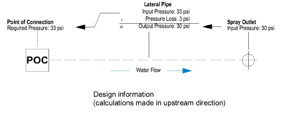
Design information tells you what the ideal pressure, flow rate, and other values are for a component. The calculations start with the system's outlets and the values that are necessary for them to operate as designed. Moving upstream, values are calculated for each component, ending with the point of connection.
The following example shows a simplified irrigation system and demonstrates how the pressure is determined for design information. The first known value is the outlet's input pressure. For the outlet to operate with the designed radius and arc, the input pressure must be 30 psi, based on the performance data associated with the selected outlet. The outlet is fed by the pipe, so the pipe must therefore have an output pressure of 30 psi. Since the pipe has a pressure loss value of 3 psi, its input pressure must be 33 psi. Lastly, the point of connection feeds the pipe, so it has a required pressure of 33 psi.
Calculated information estimates what the pressure, flow, and other values will be in the real world, with the system's given point of connection. It starts with the point of connection and the values it is expected to provide. Moving downstream, values are calculated for each component, ending with the outlets.
The following example now shows the same simplified irrigation system and demonstrates how pressure is determined for calculated information. The first known value is the point of connection's output pressure. It has been determined that the point of connection for this project will provide 40 psi. The point of connection feeds the pipe, so the input pressure for the pipe will also be 40 psi. The water is expected to lose 3 psi of pressure in the pipe, so the pipe's output pressure is 37 psi. Lastly, the pipe feeds the outlet, so the outlet's input pressure is also 37 psi. The coverage radius drawn for the outlet approximates the calculated pressure, which may be different from the design pressure radius.

Comparing the two examples, you can see that the outlet would ideally receive 30 psi of pressure, but is expected to receive 37 psi of pressure, changing the coverage radius. Similarly, the point of connection would ideally provide 33 psi of pressure, but is expected to provide 40 psi. The designer could either decide that the discrepancies between the design information and calculated information are acceptable, or could redesign the system to bring them more closely in line with each other.
When there is a problem with a component that does not achieve the required product specification conditions, or a component that is not connected to the network, a warning is generated, regardless of whether you are displaying design information or calculated information. Irrigation objects need to be connected to a network to display relevant calculated information.
As the components of the irrigation system are placed, you may need to frequently toggle between the design and calculated information methods with the Landmark > Irrigation > Toggle Design/Calculated Display command. Alternatively, the Object Info palette for every irrigation object has a Display in Drawing parameter that switches between Design Information and Calculated Information. This parameter affects the display for the entire drawing, not just for the selected object.
At any time, the irrigation parameter values of the entire drawing can be refreshed by selecting Landmark > Irrigation > Recalculate.
~~~~~~~~~~~~~~~~~~~~~~~~~