 Marionette networksMarionette networks
A network is a series of nodes connected to create a functional script, executing commands as defined by the nodes. A completed network is considered a Marionette script. All scripts read from left to right, and the data flows in one direction. Networks can only be created and edited when in Top/Plan view.
To create a network:
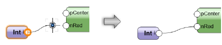
1. Using the Selection tool, click the control point on a node output port; then, move the cursor and click on a node input port.
Ensure that the Disabled Interactive Scaling mode of the Selection tool is disabled (turned off).
2. The two ports are connected by a wire. The outputs from any given node can be connected to multiple inputs on other nodes; likewise, multiple outputs can be connected to a single input node.
To neaten up a complex network, use the Align/Distribute commands to arrange the nodes; the wiring is not affected. (See Aligning and distributing objects.)
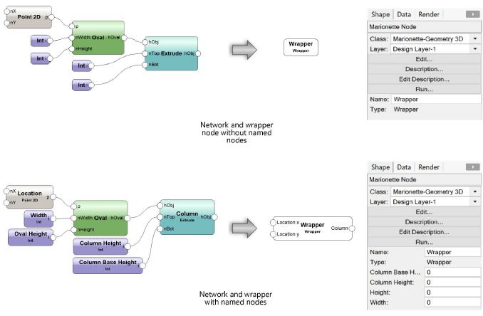
Naming nodes is an important part of creating and organizing a network, and impacts wrapper nodes significantly; for more information, see Marionette Wrapper nodes. Name input nodes and the nodes they are attached to in order to easily remember individual stages of more complicated networks. To name a node, select the node and enter a Name in the Object Info palette.
Named input nodes appear as fields on the Object Info palette of wrapper nodes; name them to quickly recognize and adjust values without having to edit the actual wrapper node.
The named inputs display in alphabetical order on the wrapper node.
The unused ports of named nodes display on wrapper nodes for easy connection to other networks. This is another good reason to name nodes.
To edit a network:
1. Select a node or wire to change.
In the network pictured above, select the wire connecting the Oval node to the Extrude node.
2. To disconnect the wire, select the control point located on the input port.
In the network pictured above, select the control point located on the profile (Obj) input of the Column node.
3. Connect the wire to a different input port, or remove the wire by clicking in a blank area of the drawing.
If a node is deleted, all associated wires are also deleted.
|
Command |
Path |
|
Run Marionette Script |
Context menu |
To run the Marionette script, right-click on any node in the network and select the command. Alternatively, click Run on the Object Info palette.
If an error occurs when running the script, an Execution Error dialog box opens, providing information about the type of error and its location in the script.
Objects created by running the script are grouped when the script completes execution. Running a script consecutive times replaces grouped objects created from the previous execution of the script; to retain the objects, rename the group or ungroup the objects.
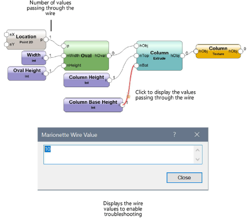
The Debug mode of the Marionette tool enables the troubleshooting of networks when they are not functioning as desired. In debug mode, a number appears next to each output port, representing the number of values traveling from that output port to any attached input ports. Clicking on a wire opens the Marionette Wire Value dialog box, displaying the values that travel through the wire. The script executes upon closing the dialog box.
To cache the wire values, click Preferences, and select Cache Last Run in Debug Mode. With this mode enabled, you can view the wire values without re-executing the script.
~~~~~~~~~~~~~~~~~~~~~~~~~