The ConnectCAD® suite creates schematic network diagrams of electronic wiring and connections between equipment for any type of connected system, such as IT networks, or broadcast, audio/visual, or lighting systems. The schematic diagram of electronic devices, their connections, and their cables indicates the flow of signals through a system; different types of signals are color-coded. In addition to the schematic view, layout drawings (made to scale) show the physical position of equipment in racks and console bays. All elements are labeled and can be compiled into detailed lists of required cables, components, and parts.
With a ConnectCAD license, the ConnectCAD suite of tools and commands is available from the ConnectCAD workspace. This workspace, along with an associated template, contains the needed functionality for creating schematic diagrams and layout drawings.
 Workflow: Using ConnectCAD
ConnectCAD automates much of the tedious work of creating schematic diagrams and layout drawings.
● Follow the information in Getting started to set up the file.
● Optionally, select a ConnectCAD template.
● Specify default ConnectCAD settings.
● Set the design layer scale.
● Enable the snap grid on the Snapping palette. The snap grid setting controls the spacing of schematic objects such as devices, sockets, circuits and their related text and graphics. Setting the snap grid appropriately with the layer scale ensures neat presentation of connectivity diagrams. You can draw a schematic on, for example, a 1:50 layer and if you’ve set the snap grid accordingly (100 mm in this example), the schematic objects display correctly.
● Large projects may require project sharing, so that different teams, such as audio, video, and control teams can all work on the same file. See Project sharing for more information. When setting up for project sharing, keep everything in a single file divided into layers according to discipline. Use the Connect tool in Arrow mode to connect devices on the same or different layers.
● Work on the schematic drawing, diagramming how equipment is connected to form a system.
● Place the needed devices. Initially, place basic devices that you customize, or use the Device Builder tool to help create custom devices. Later, when you have a library of custom device symbols, place these symbols with the New Device tool.
● Add sockets to the devices. Signals normally flow from left to right.
● Duplicate similar devices to quickly add them to the drawing.
● Use the Connection tool to link the devices, from the output sockets of a device to the input sockets of the next device, creating a circuit.
● Place specialized devices.
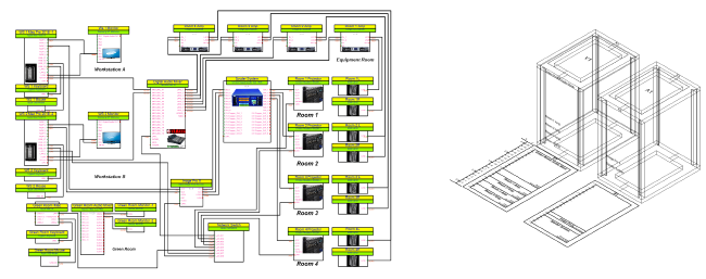
● Work on the layout drawing, with the physical positions of equipment in racks and bays.
● Create a layout room (optional).
● Create 2D equipment racks, and add equipment items to them; modular equipment items are placed in rack frames. The process of adding devices from the schematic layer can be automated.
● Create 3D versions of the layout.
● Verify that the drawing is correct; refresh labels and numbering of the drawing objects if needed.
● Sheet layer viewports are automatically created for client presentations.
● Create worksheets for reporting purposes.
~~~~~~~~~~~~~~~~~~~~~~~~~