 Placing connector
panelsPlacing connector
panels
Placing connector
panelsPlacing connector
panelsTool |
Tool set |
Connector Panel
|
Schematics |
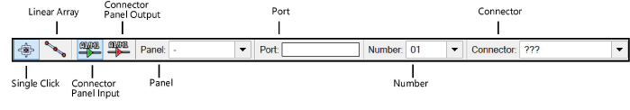
The tool places audio or video connector panels. Panels can be associated with equipment items in the layout view; see Creating connector panel layouts.
Mode |
Description |
Single Click |
Places a single connector panel at the click location |
Linear Array |
Places an array of connector panels along the drawn line |
Connector Panel Input |
Inserts an input type of connector panel |
Connector Panel Output |
Inserts an output type of connector panel |
Panel |
Select the panel name for the connector panel location. If the panel does not yet exist, create a new one by selecting New. Enter the new panel name in the Add New Panel dialog box. |
Port/Number |
Assign a port code and number combination. The port name must be unique for each device. |
Connector |
Select the connection type |
To insert a terminal panel or DIN rail panel:
1. Click the tool, and select the placement mode.
2.From the Tool bar, select the type of connector panel to place by clicking the mode.
On the drawing, green indicates an input connector, and red indicates an output connector.
3.Enter the Port number.
4.Specify the Panel and Number by selecting the values from the lists on the Tool bar. Create a new panel if needed.
If you continue placing the same connector panel device, the Number automatically increments.
5.Click to place the connector panel into the drawing. If placing the device into an existing circuit, the device splits the circuit.
● In Single Click mode, click once to place the object.

● In Linear Array mode, click once to start the array; move the cursor to set the distance and direction of the linear array. Press the Shift key to constrain to the horizontal or vertical direction. The preview indicates the spacing and placement of the objects; the floating Data bar shows the Count. Click to place them.
The device can be edited later from the Object Info palette.
![]() Click
to show/hide the parameters.
Click
to show/hide the parameters.
~~~~~~~~~~~~~~~~~~~~~~~~~
