 Creating a vertical section viewportCreating a vertical section viewport
Command |
Path |
Create Section Viewport |
● View ● Context menu |
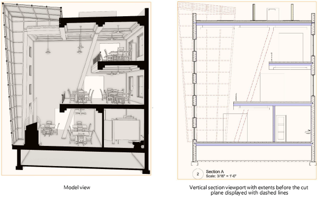
Vertical section viewports create a cross-section view of a model that can be customized in several different ways, as outlined in Creating section viewports.
To create a vertical section viewport:
1. Prepare to create the viewport as follows:
● To create a section view from an active design layer, set the layer to Top/Plan view by selecting View > Standard Views > Top/Plan.
● To create a section view from an existing viewport, either select a non-sectioned viewport object in Top, Bottom, Left, Right, Front, or Back view orientation, or edit the annotations of a non-sectioned vertical viewport or horizontal section viewport.
● To create a section view from an existing clip cube object, use the Selection tool to highlight a vertical face of the clip cube where the section will begin. (See Viewing a model with the clip cube.)
2.Do one of the following:
● Select the command.
● Create a section line with the Section-Elevation Line tool and then either select the command or click Create Section Viewport from the Object Info palette. (See Creating section-elevation lines.) Skip to step 4.
● Duplicate an existing section line from another viewport. The copy retains all the settings and attributes of the parent section line, but is no longer linked to the viewport. Position the line, and then either select the command or click Create Section Viewport from the Object Info palette. Skip to step 4.
● From an active clip cube, select the face to serve as the cut plane, and then right-click on the face and select the command from the context menu. The section-elevation line is created automatically; skip to step 4.
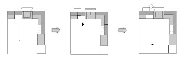
3.If you’re not using an existing section-elevation marker or clip cube to create the cut plane, draw the section line on the design layer or viewport.
Click in the drawing and drag the mouse to begin drawing the marker line. Click to mark the end of the line, and then click to indicate the side of the line to look toward (keep), which is indicated by a black arrow. Double-click to end the line.
To create a broken section line, click in the drawing and draw the first segment. Indicate which side of the drawing to show in the viewport. Click and drag to draw additional segments; broken section line segments are always parallel or perpendicular to each other (90° angles). Double-click to end the broken line.
4.The Create Section Viewport dialog box opens. The available parameters depend on whether you choose to place the section viewport on a sheet layer or design layer. The settings can be edited later from the Object Info palette or by right-clicking on the viewport and selecting Properties from the context menu.
The scale of a design layer section viewport is the same as the layer where it is placed. The rendering mode of the current layer is also used to render the design layer section viewport.
![]() Click
to show/hide the parameters.
Click
to show/hide the parameters.
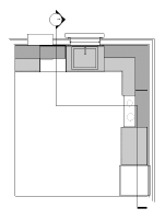
The new vertical section viewport is displayed.
For a viewport placed on a design layer, the view is initially set to Top/Plan, but the section can be displayed in any view. A design layer section viewport can be cropped, but it does not contain an annotation space.
~~~~~~~~~~~~~~~~~~~~~~~~~