 Inserting pipe-and-drape assemblies
|
Mode |
Tool |
Workspace: Tool set |
|
Modes for the Polyline tool |
Soft Goods
|
Design Suite: Detailing Spotlight: Event Design |

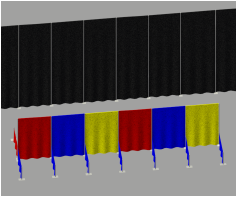
The Soft Goods tool creates pipe-and-drape assemblies typically used in event planning, such as when creating temporary booths in a convention center. To draw a pipe-and-drape assembly, either use the Soft Goods tool, or create a closed 2D shape and then select the Create Objects from Shapes command (see Creating objects from shapes).
To display hanging points for soft goods objects, enable Hanging Point Classes in the Braceworks preferences (see Braceworks preferences).

|
Mode |
Description |
|
Polyline creation options |
Selects the method for drawing the polyline upon which the object is based; see Creating polylines |
|
Soft Goods Style |
Opens the Resource Selector to select a resource for placement; double-click a resource to activate it |
|
Preferences
|
Sets the default parameters that are used for each new curtain or truss border |

Click the tool and mode.
Do one of the following:
Click Soft Goods Style on the Tool bar to select a resource from the Resource Browser.
Click Preferences to open the object properties dialog box and specify the tool's default parameters; select Pipe-and-Drape from the Function list.
The parameters can be edited later from the Object Info palette.
Click to show/hide the parameters.Click to show/hide the parameters.
|
Parameter |
Description |
|
Style |
Replace, remove, or edit the current style, or create a new plug-in object style for this object. Editing a style changes all instances in the file that use the style. |
|
Hide style parameters (Object Info palette only) |
Hides the parameters that are set by style; these cannot be edited from the dialog box or Object Info palette |
|
Function |
Select Pipe-and-Drape (for curtains or borders, see Inserting curtains and borders) |
|
Adjustable Length |
Specifies the length of a straight pipe-and-drape assembly |
|
Height |
Indicates the height of the pipe-and-drape assembly |
|
Show centerline |
In Top/Plan view, displays the center line of the pipe-and-drape assembly |
|
Double wall |
Creates a double-wall assembly, by offsetting the first curtain, drawing a second parallel curtain, adding double curtain hardware, and doubling the number of sliders and amount of material required |
|
Show slider(s) |
Draws the soft goods slider segments at the top of the assembly |
|
Slider Options |
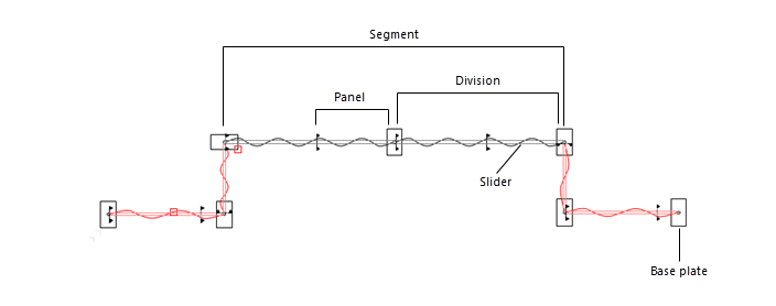
The number of sliders (divisions) created depends on the length of the entire assembly, the selected Slider Options range, and the Target Length specified. Select from a list of standard slider size ranges, or select Custom to create a non-standard slider size, and enter the Divisions per Segment to include. |
|
Target Length |
For standard Slider Options ranges, enter the ideal slider length. If the value entered falls within the selected Slider Options range, the tool calculates the best length based on even divisions of the total Pipe-and-Drape run length. If the value entered falls outside the selected range, the tool adjusts the value to fit within the range. |
|
Divisions Per Segment |
For Custom Slider Options, enter the number of divisions per segment |
|
Actual Length |
Displays the actual calculated slider length used; for a multiple-segment object with different slider lengths, the parameter indicates widths vary |
|
Division Total |
Displays the total number of divisions in the assembly |
|
Highlight non-standard slider segments |
Highlights slider segments of a non-standard length |
|
Running Length |
For multiple segment assemblies, displays the total length of the pipe-and-drape assembly |
|
Hardware to Include |
Select which types of hardware to draw and count |
|
Base Options |
Select from a list of standard base plate sizes, or choose the rounded boom base |
|
Base Diameter |
For the round boom base option, indicates the diameter of the boom base |
|
End Hardware |
Select whether to include end hardware (base plate and upright) at each end of the assembly |
|
Base Pin Location |
Select the pin/upright's position on the baseplate relative to the object's path |
|
First Base Shift |
When a base plate is included at the start of the assembly, select whether it is centered on the upright (None), or shifted towards the inside (In) or outside (Out). This option does not apply to a boom base. |
|
Last Base Shift |
When a base plate is included at the end of the assembly, select whether it is centered on the upright (None), or shifted towards the inside (In) or outside (Out). This option does not apply to a boom base. |
|
Base/Upright Color |
Displays the base/upright color or texture specified on the 3D Options dialog box, Hardware pane. |
|
Slider/Upright/Double Wall Hanger/Base Total |
Displays the number of sliders/uprights/double wall hangers/base plates in the assembly |
|
Show 3D uprights |
Displays the upright hardware in 3D views; deselect this option to create seamless pipe-and-drape instances |
|
Stock Drape Width |
Specifies the width of an individual drape panel |
|
Minimum Overlap |
Indicates the total distance of drape overlap for adjacent drape panels |
|
Vertical Tied Fullness % |
Sets the overlap percentage at each curtain tie, and affects the Total Drape Count |
|
Total Drape Count |
Displays the number of drape panels required based on the specified stock drape width |
|
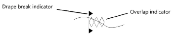
Show drape breaks |
Places markers where each drape ends and the next one starts |
|
Show overlap |
Indicates where the drapes overlap
|
|
Drape Clips |
Enter data about drape clips, if needed |
|
Sandbags |
Enter data about sandbags, if needed |
|
Simple 2D |
Simplifies the Top/Plan view of the pipe-and-drape assembly, showing it as a line |
|
Simple 3D |
Simplifies the 3D view of the pipe-and-drape assembly, showing it as a flat surface |
|
Pleat Width (Visual Only) |
Indicates the distance between pleats |
|
Pleat Depth (Visual Only) |
Indicates the depth of the pleats |
|
Flip pleats (visual only) |
Switches the positive and negative portions of the pleats |
|
3D Options |
Opens the 3D Options dialog box, for setting the appearance of the pipe-and-drape assembly in 3D; see Setting soft goods 3D display options |
|
Current Drape Option |
Displays the currently selected front and, if available, back 3D curtain option from the 3D Options dialog box |
|
Materials and Finishes |
|
|
Main Material Type |
Enter notes about the pipe-and-drape assembly's front and, if applicable, back main material (does not affect the drapery appearance) |
|
Color |
Enter notes about the pipe-and-drape assembly's front and, if applicable, back material color (does not affect the drapery appearance) |
|
Weights |
|
|
Final Total Weight |
Enter the total weight; the Final Distributed Weight is automatically calculated based on the current settings |
|
Final Distributed Weight |
Enter the distributed weight; the Final Total Weight is automatically calculated based on the current settings |
|
Position |
Displays the name of the associated rigging object, if the pipe-and-drape assembly is attached. Optionally, attach this object to a rigging object, or change the rigging object association, by entering the Position Name of the rigging object. Delete the name to break the association. For other methods to attach loads, see Making the attachment. |
|
Purpose |
Enter notes about the object's purpose |
|
Container ID |
Enter notes about the object's container ID |
|
Vendor |
Enter notes about the object's vendor |
|
Cost |
Enter notes about the object's cost |
|
Note |
Enter any miscellaneous information required, such as stock number or other data |
|
Text Options |
Opens the Text Options dialog box, to enable the display and format the text of labels; see Formatting soft goods object labels |
|
Default Text Positions |
Text labels can be moved by dragging their control point; this option returns them to their default locations |
|
Parts Classes |
Opens the Parts Classes dialog box, to specify class naming for the various parts of the soft goods object. This allows parts of the soft goods to be set to visible, grayed, or invisible. Use the standard class, select a class from the list of classes present in the drawing, or create a new class. Select <Soft Goods Class> to place the soft goods element in the same class as the soft goods object. Class Prefix: Specifies an optional default root class naming standard for all soft goods parts; click Assign Default Classes With Prefix to begin all soft goods class names with the prefix, so that they are sorted together. Assign Default Classes With Prefix: Sets the class names for all soft goods elements to the standard, using the Class Prefix if there is one. Soft goods parts: For each part of the soft goods object, specifies the class name standard; the class names shown here are applied to the parts. Parts classes for the soft goods styles are controlled as a group. If Parts Classes is set by style, the dialog box is inaccessible and the settings cannot be changed for individual instances. If Parts Classes is set by instance, all settings can be changed. |
|
Update (Object Info palette only) |
Updates the object |
|
Load Information |
A soft goods object is considered to be a distributed load in Braceworks calculations; the pipe-and-drape line needs to be parallel to the rigging object. Load information is used for Braceworks calculations and reports (Braceworks required). |
|
Include in Calculations (Braceworks required) |
Includes the soft goods object in Braceworks calculations; deselect to exclude the object from participating in structural calculations |
|
Load Group Name |
The load category is always Scenery for soft goods objects |
|
Load ID |
Enter a unique ID for the load for informational use in reports |
|
Load Name |
Identifies the object in load calculations |
|
Distributed Weight |
Displays the distributed weight of the soft goods object |
|
Total Weight |
Displays the total weight of the object |
|
Vertex Parameters |
Edits the vertices of the path object that the curtain is based upon; see Editing vertex-based objects |
Click to set the soft goods object’s start point.
Click to set the end of the segment and the beginning of the next. Continue drawing segments in this manner until the pipe-and-drape assembly is complete, and then double-click.
Once created, the soft goods object can be edited by selecting the object, and then selecting Modify > Edit Soft Goods. Reshape the soft goods polyline with the Reshape tool; click Exit Profile to return to the drawing.
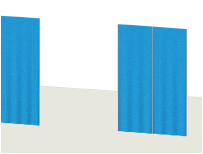
To create an opening in the pipe-and-drape assembly, edit the vertex parameters from the Object Info palette. Select the vertex prior to the opening as described in Editing vertex-based objects, and then click Hide Next Edge.
Optionally, create a style resource for the object (see Standard plug-in object styles without catalog options).
