 Inserting a photometric grid
|
Tool |
Tool set |
|
Photometric Grid
|
Lighting |
The photometric grid is a three-click rectangular object, and can be inserted in Center-line Placement mode or Edge Placement mode. The grid can be tilted, accounting for sloped or raked stages.
![]()
|
Mode |
Description |
|
Center-line Placement
|
Click once, and then again, to define the length through the center of the grid. Click again to specify the grid width. |
|
Edge Placement
|
Click once, and then again, to define the length along the edge of the grid. Click again to specify the grid width. |
|
Preferences
|
Sets the default preferences for the photometric grid |

To insert a photometric grid:
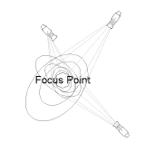
Ensure that each lighting device contributing to the illumination has an assigned focus point; see Creating a focus point object.
To perform calculations without drawing light beams, disable Calculate Using Only Visible Beams in the photometric grid properties.
Click the tool and mode.
Click in the drawing area to insert the photometric grid.
The first time you use the tool in a file, a properties dialog box opens. Set the default parameters. The parameters can be edited later from the Object Info palette.
Click to show/hide the parameters.Click to show/hide the parameters.
|
Parameter |
Description |
|
Rotation |
Specifies the number of degrees to rotate the object (0.00 is horizontal) |
|
Text Style |
Select a text style from a library or the current file. To use the style defined for the object’s class, select <Class Text Style>. To format the text using options on the Text menu, select <Un-Styled>. See Using text styles and Formatting text. |
|
Show Elevation |
Displays the grid elevation along with the photometric values |
|
Show Zero |
Displays elevation values of zero |
|
Show 3D Labels |
Displays photometric labels in 3D views, along the plane created by the grid |
|
Calculate Using Only Visible Beams |
Determines the photometric values based on only the lighting devices with Draw Beam selected; this reduces calculation time |
|
Use Threshold Settings |
Displays each photometer in the grid according to a color that corresponds to the specified threshold ranges |
|
Grid Spacing X |
Specifies the spacing of photometric values in the X direction |
|
Grid Spacing Y |
Specifies the spacing of photometric values in the Y direction |
|
Grid Width X |
Specifies the length of the grid in the X direction; available in Object Info palette only |
|
Grid Width Y |
Specifies the length of the grid in the Y direction |
|
Slope Based On |
To tilt the grid, select whether to specify slope values by angle or offset distance coordinates, and enter the angles or offset distances |
|
Tilt Angle X/Y |
When the grid slope is based on angle, specify the slope angle in the X and Y direction. If specified by distance, the calculated angles display. |
|
Height Offset X/Y |
When the grid slope is based on distance, specify the total height offset in the X and Y direction. If specified by angle, the calculated offsets display. |
|
Threshold Settings |
Opens the Threshold Settings dialog box, to specify the threshold values and the colors for the threshold ranges |
|
Refresh |
Refreshes the grid display after changes have been made to the lighting conditions |
After placing the photometric grid, set the grid’s Z value from the Object Info palette; illumination values vary depending on the grid’s elevation.
