 Concept: Power schematics
Difficulty level: Advanced
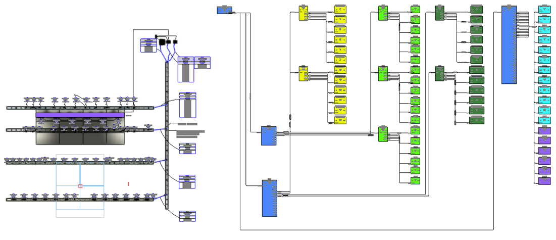
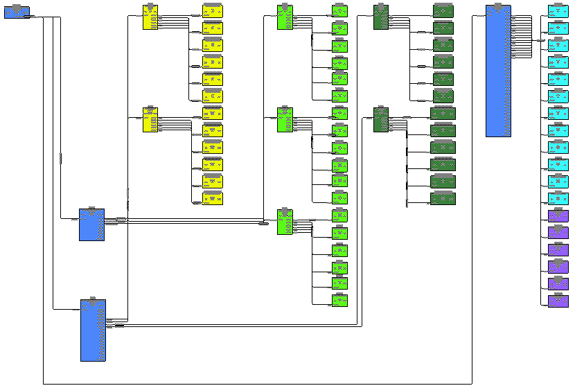
A power schematic consists of a schematic view of all the objects on a light plot that participate in power calculations. The light plot and power schematic views show the same objects, but in different ways. Light plots are to-scale drawings of the physical world. Schematics, on the other hand, are laid out to illustrate the flow of signals. This feature combines the light plot expertise of Spotlight with the schematic abilities of ConnectCAD.
The schematic shows a left-to-right signal flow, with devices at the same hierarchical level displayed in columns. Devices are arranged to minimize the number of circuits that cross over each other.

Light plot (left) and power schematic (right)
The Create Power Schematic command produces a power schematic from the light plot. The command:
Searches selected layers for objects that participate in power calculations
Detects the Spotlight lighting devices and distributors
Creates schematic devices for the lighting devices and distributors on the specified layer
Adds sockets to the devices. The number of sockets added is based on the distributor ports available. Sockets are named according to Spotlight conventions.
Adds circuits to connect the devices if the lighting devices and distributors have already been power patched or are connected by cables. Circuits are associated with cables on the light plot.
Creates an association between the lighting devices and distributors on the light plot and the devices on the schematic. Lighting devices that are connected in a daisy chain configuration display with socket loops in the power schematic; the power consumption of all daisy chained lighting devices is summed at the distributor.
The command can also update an existing power schematic and refresh the calculated power values. If devices or circuits already exist, the command does not duplicate them.
Power records from lighting devices and distributors are attached to their associated schematic devices to track the signal flow (see Power patching the electrical system). Linked text (see Linking text to record formats) in the devices shows the values of the power record fields.
If lighting devices, distributors, and cables on the light plot are edited, the associated devices and circuits on the schematic are updated. Similarly, if devices and circuits are edited on the schematic, the associated lighting devices, distributors, and cables on the light plot are updated. Spotlight cable preferences (see Setting cable preferences) control whether cables are added automatically to the light plot.
If a cable or connection is deleted from the light plot, a markup polyline indicating the deletion replaces the circuit on the schematic. Similarly, if a circuit is removed from the schematic, a polyline replaces the cable on the light plot. To remove markups, select the Clear Markup command (see Clearing drawing markup).
The Create Report command can create many types of worksheets and schedules to report on power usage. Update the power worksheets after you select the Power Schematic command. You can also use data visualization to check for errors such as overloaded circuits.
Specifying power schematic settings
|
Command |
Workspace: Path |
|
Power Schematic Settings |
Design Suite: Entertainment > Cable/Power Planning Spotlight: Spotlight > Cable/Power Planning ConnectCAD: Layout |
Before creating the power schematic, set up the default power schematic settings. The settings apply to the current file.
To specify the power schematic settings:
Select the command.
The Power Schematic Settings dialog box opens.
Click the General Settings pane to set global default parameters.
Click to show/hide the parameters.Click to show/hide the parameters.
|
Parameter |
Description |
|
Schematic Objects Grid |
Controls the initial size of the objects in the schematic |
|
Symmetrical |
Constrains the Y setting to be the same as the X setting, resulting in a symmetrical grid |
|
Grid X / Grid Y |
Sets the grid dimensions in the X and Y directions; the Y setting is grayed if Symmetrical is selected |
|
Device Units |
|
|
Power |
Specify watts or kilowatts for device power requirements |
|
Weight |
Select the units for weight measurements (use kilograms for best results) |
Click the Cable Lengths pane. You can modify the list of default cable lengths for circuits; select the Cable Length from the Object Info palette of a selected circuit.
Click to show/hide the parameters.Click to show/hide the parameters.
|
Parameter |
Description |
|
Cable Lengths list |
Lists the available cable lengths. Edit any entry inline. |
|
Add |
Adds a new cable length to the list; the new cable length is saved in the user folder. Edit the line for the new entry inline by entering the desired new cable length. |
|
Delete |
Removes the selected entry from the list |
|
Restore Defaults |
Restores the default cable lengths |
Creating a power schematic
|
Command |
Workspace: Path |
|
Create Power Schematic |
Design Suite: Entertainment > Cable/Power Planning Spotlight: Spotlight > Cable/Power Planning ConnectCAD: ConnectCAD > Layout |
This command creates a power schematic based on the lighting devices and distributors in the selected layers. The command also updates an existing power schematic and refreshes the calculated power values.
The command can also update an existing power schematic and calculated power values. If devices or circuits already exist, the command does not duplicate them.
The devices in the schematic are connected automatically if the lighting devices and distributors have already been power patched or are connected by cables. See Power patching the electrical system.
You can also patch the objects later. Circuits are automatically created on the schematic, or cables are added to the light plot, as patching occurs. The option to Automatically create cables when devices get connected must be selected in the Cable Preferences dialog box; see Setting cable preferences.
Select the Power Patch Selected Objects command to patch selected lighting devices; circuits are automatically created for the associated devices on the schematic layer. (See Power patching by command.)
Select the Connect Selected command to connect selected devices (or draw circuits with the Connect tool), to automatically draw cables and power patch the associated objects on the light plot. (See Connecting circuits automatically.)
To create a power schematic:
Select the command.
The Create Power Schematic dialog box opens.
Click to show/hide the parameters.Click to show/hide the parameters.
|
Parameter |
Description |
|
Layers list |
Select the layers with lighting devices and distributors to use as the basis of the power schematic. A check mark in the Use column indicates that the layer will be included. |
|
Select All Layers/Deselect All Layers |
Either select all of the layers, or deselect all of the layers |
|
Destination Layer |
Indicates the layer on which to create the power schematic |
A ConnectCAD device is created for each unique lighting device and distributor object and placed in the specified layer. (See Placing a basic device or device symbol.)
If needed, adjust location of the devices in the schematic.

Showing Spotlight objects associated with devices
To display the Spotlight object associated with a schematic device:
Select the schematic device.
From the Object Info palette, click Show Spotlight Object.
The view switches to the light plot layer if needed, zooms in on the object, and selects it.
