Quick Start: Let's model a 3D solid object
Difficulty level: Beginner
Many Vectorworks Design Suite tools automatically create 3D objects, like walls, plants, and rigging objects. Vectorworks also includes several tools and commands that let you manually create custom 3D objects for 3D printing, decorative features, and other purposes. Perhaps the most basic kind of 3D modeling in Vectorworks is solid modeling. In this topic, you'll learn how to combine a variety of tools and commands to create and shape a basic solid object. For a more general overview of 3D modeling in Vectorworks, see Concept: 3D modeling.
The location of commands and tools varies, depending on the workspace. You can learn to use the Quick Search feature to quickly find commands or tools; see Quick Search. You can also look at the Commands and tools PDF here in the Vectorworks help system.
Explore 3D views
To get comfortable with working in a 3D environment, you'll create a basic extrude and view it from different angles.
Select the New command to open a new blank file, which should open in Top/Plan view.
Use the Rectangle tool  to draw two rectangles, side by side.
Select one of the rectangles, and then select the Extrude command. The Create Extrude dialog box opens; enter a height for the extrusion. (Pick a height that makes sense for your drawing's scale and the rectangle's size.) The Object Info palette indicates the object is now an extrude, and you can edit the extrude's dimensions there.
Next, let's change the 3D view, so you can see the difference between the objects. Use the Onscreen View Control cube in the lower left corner of the drawing area or the Flyover tool  to dynamically change the view and see objects from all angles.
The Onscreen View Control cube lets you view both planar and 3D objects from any angle
There are several other ways to set views in Vectorworks, as described in the Viewing the drawing section of the Vectorworks help system.
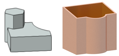
Add and subtract solid objects
One plain rectangular extrude isn't a very impressive 3D object. Let's combine a few extrudes to make something more interesting.
Use the Circle tool  , Regular Polygon tool
  , and/or other tools that create basic shapes, and the Extrude command, to create a cluster of overlapping extrudes. You need to defy the laws of physics for the next commands to work correctly; make sure the extrudes overlap.
Alternatively, in a 3D isometric view, draw the 2D shape, and immediately use the tool's Push/Pull mode to interactively create an extrude.
Press the Shift key and use the Selection tool  to select two of the overlapping extrudes. Then select the Add Solids command. The two extrudes are combined to create a single solid object; the Object Info palette shows it is now a solid addition.
Next, select the solid addition and an overlapping extrude. Then select the Subtract Solids command. The Select Object dialog box opens. Click the arrows  until the solid addition object that you want to retain is highlighted, and then click OK. The object to subtract is removed, as is the area of the solid addition where the objects overlapped. The Object Info palette shows the object is now a solid subtraction.
Now that you have a feel for a few solid modeling basics, let's see how we can combine tools and commands to create an actual object.
Design a utensil holder
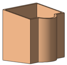
In this example, we'll use a combination of tools and commands to model a utensil holder for a kitchen counter or a desk.
Select the New command to open another new blank file in Top/Plan view. Make sure the drawing scale and/or zoom is appropriate for working with an object measured in millimeters or inches.
Use the Rectangle tool to draw a rectangle of 230mm wide by 180mm deep (about 9" wide by 7" deep).
To give the holder a more interesting shape, use the Circle tool to draw a circle that overlaps with the rectangle. The goal here is to add a curve to the utensil holder's footprint, so the front face won't be flat.
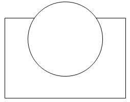
Select both the rectangle and the circle, and then select the Add Surface command. The two objects are combined into one, and the Object Info palette shows it's a polyline.
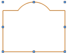
With the shape still selected, on the View bar, select Right Rear Isometric from the Current View/Standard Views list.
Alternatively, press 9 on your numeric keypad, or use the Onscreen View Control cube, to switch to that view.
Click the Push/Pull tool  , and place the cursor over the polyline, which highlights to indicate it's ready to be pushed or pulled. Click the shape and move the cursor upward; the preview of the extrude displays. Click again to set the height of your utensil holder, about 215 mm (8.5 inches).
Next, let's angle the top, so the back of the utensil holder will be slightly higher than the front. Select the Taper Face tool  . Move the cursor over the front face until one of the flat segments highlights, and click on the face, to set it as the pivot point for the taper operation. Move the cursor over the top face, which highlights, and click again to select it as the face to taper. Move the cursor as the preview of the taper operation displays. Click to set the taper at the desired angle.
The Object Info palette now says the object is a generic solid.
Select the Shell Solid tool  , and click Preferences
  from the Tool bar. In the Shell Solid Preferences dialog box, select to create the shell to the inside of the object's face, and enter a thickness for the shell wall of 13mm (.5 inch). Move the cursor over the top of the solid object, which highlights to indicate it can be selected for the operation. Click the face, and then press Enter or click the check mark button on the Tool bar.
The Object Info palette says the object is now a shell.
Let's give the utensil holder a little color. With the utensil holder selected, go to the Fill section of the Attributes palette. Set the Fill Style to Solid, and then click the fill selector and select a color from the color palette; if you want different color options to choose from, click the Active Palette button and select a different color palette.
You've designed a utensil holder.
Optionally, use the Onscreen View Control cube or the Flyover tool (shown in this video) to dynamically change the view. At this point, you can take a peek at the bottom of the object to see that the shell operation didn't create a hollow tube, but left the bottom of the utensil holder intact.