 Quick Start: Let's design a house
Difficulty level: Beginner
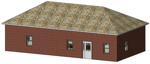
With a few clicks, you can start designing a simple concept house in Vectorworks. Use this topic to help you understand how to draw in Vectorworks, place objects, view objects, add textures to objects, and to get used to the interface. The house we'll create is just a representation of an actual building, but it will help you get going!
The location of commands and tools varies, depending on the workspace. You can learn to use the Quick Search feature to quickly find commands or tools; see Quick Search. You can also look at the Commands and tools PDF here in the Vectorworks help system.
Draw the walls and floor
Select the New command to open a new, blank file.
The drawing opens in Top/Plan (2D) view.
Click the Wall tool  .
.
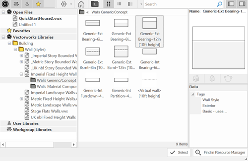
From the Tool bar, click the Wall Style list, and select a generic exterior wall (either Imperial or metric, depending on your unit preference) from the Resource Selector. Ensure that the wall is from a fixed height library, and not from a story bound library. Either double-click, or click Select, to choose the wall style.
Click in the top left corner of the drawing area. Press the Tab key, and enter a length value (L) in the floating Data bar, such as 48' (14.6 m). Press Enter to set the value. Move the mouse to the correct length as indicated by the dotted circle (a snapping indicator), and click to place the first wall.
Press the Tab key and enter the next value (such as 24' or 7.3 m) to begin creating a rectangle with the walls. Place the second wall, and then the third and fourth walls, to complete the rectangle. If you pause the cursor over the start of the first wall, you will get SmartCursor cues (snapping indicators) to help you draw the third and fourth wall.
You should see four walls in a rectangle shape.
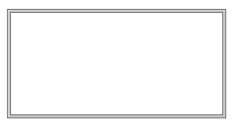
Four connected walls
Click the Slab tool  and click Inner Boundary mode
  from the Tool bar. Select a floor Slab Style such as Slab on Grade-6in w/Gravel.
Click within the walls to place the floor slab.
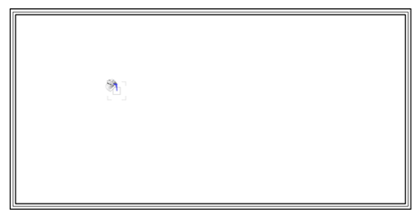
Placing a floor slab
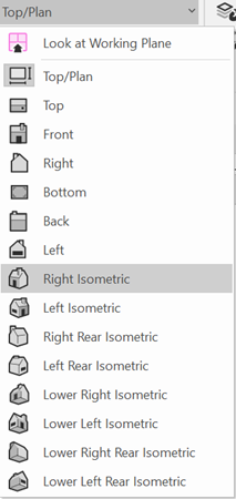
On the View bar, select Right Isometric from the Current View/Standard Views list, or just press 3 on your numeric keypad or use the Onscreen View Control cube to switch to a 3D view.
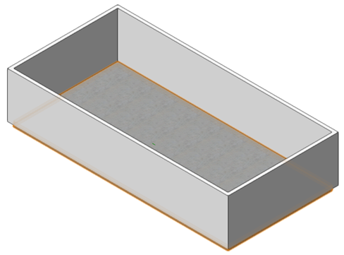
Four walls and a floor
The walls should extend to cover the slab on the exterior of the house. Click the Select Similar tool  , and click on a wall. This selects all of the walls.
In the Object Info palette, enter a Bot Offset value of -1' (-0.3 m).
Add doors and windows
Click the Door tool  and select a front Door Style. Click in a wall to position the door. Click again to place the door.
Select a patio door style and place it in the opposite wall.
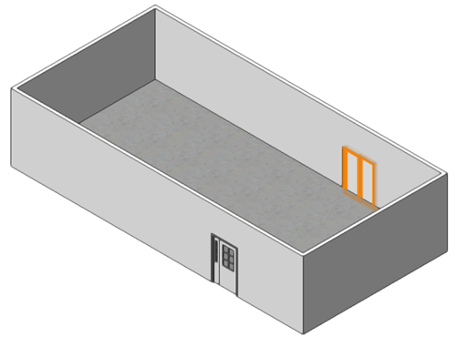
Adding a front and back door
Click the Window tool  and select a simple Window Style such as single or double hung. Click to position a window, and click again to place it. Place windows into the walls where you would like. The walls highlight as you move the cursor over them, so you know where they will go.
If you get a resource conflict message, because you already have a clear glass texture from when you inserted a door, for example, select Replace the texture in the current document.
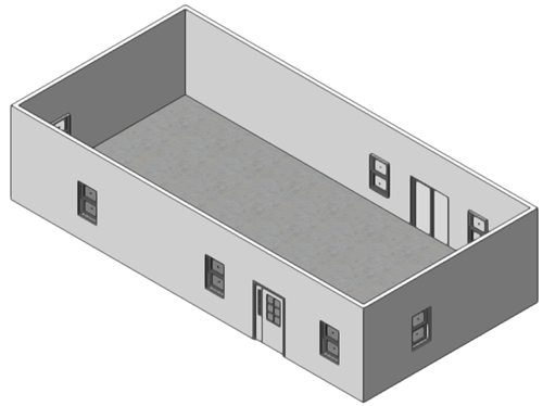
We now have windows and doors
Add interior objects
Switch to Top/Plan view by selecting it from the Current View/Standard Views list on the View bar, or by pressing 0 on the numeric keypad or using the Onscreen View Control cube.
Open the Resource Manager (Ctrl+R (Windows) or Cmd+R (Mac)) if it's not already open. In the Resource Manager, search for the term "layout." Select the Interior Kitchen L shape layout symbol, and place it in a corner of the house. We switched to a 2D view because it's easier to slide any windows that might be in the way. If you need to move any windows, select one and drag it to a new position within the wall.
The layout symbols are a quick way of placing several pre-configured objects like cabinets, sinks, and more. As you become more familiar with Vectorworks, you'll see that you can place and customize individual object types or select from a variety of manufacturer styles.
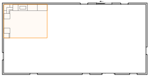
Adding a kitchen symbol
Place the Living Room 04 symbol into the house. What a nice, open concept home we have already! You could get fancy and place some interior walls and doors if you like.
The living room symbol contains some lights. You can hide the light source objects by going to the Display pane of Vectorworks preferences and selecting Only in Wireframe or Never for Display Light Objects.
Press 3 on the numeric keypad to return to right isometric view (or select the view from the Current View/Standard Views list on the View bar).
Add realistic textures and light
Let's add some textures for a realistic appearance. Click on the floor slab with the Selection tool  . From the Render tab of the Object Info palette, select a carpet texture for the Slab on Grade component of the slab. You can find some commonly used textures in the Textures.vwx file in the Resource Selector.
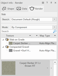
Select a carpet texture for the slab portion of the slab object
Click the Select Similar tool  , and click on a wall. This selects all of the walls.
From the Render tab of the Object Info palette, choose an exterior texture (like a brick texture) for the left (outer) components of the walls and choose an interior texture for the right (interior) components of the walls. The way we originally drew the walls determines which side is the exterior.
In the Object Info palette, in the Mapping area of the Render tab, you may want to adjust the Scale of the brick texture to make the bricks larger.
We used a generic wall style so that we could learn how to apply textures. Other wall styles have textures built in.
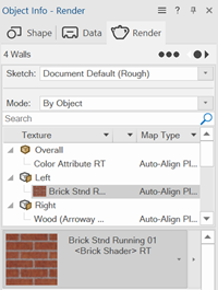
Select a brick texture for the left portion of the walls, and a wood texture for the right portion of the walls
The living room symbol contains lights; when we added them to the drawing, that turned off the default lighting. Let's add a little sunshine. Click the Light tool  in Directional Light mode
  . Click in the upper left corner of the drawing. The light object won't be visible if we adjusted the preferences to display it, but its effects are instant.
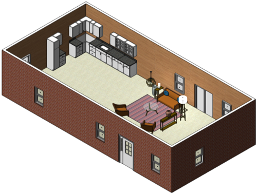
Practically ready to move in!
Add a roof and finish up
We're almost done with our concept house. Let's add a roof, on another design layer.
Select New Design Layer from the Active Layer list on the View bar. Accept the defaults.
We're now on Design Layer-2, and we want to be able to see and click on objects in Design Layer-1. Select the View > Layer Options > Show/Snap/Modify Others command.
Select the four walls like we did earlier, and then select the Create Roof command.
In the Create Roof dialog box, change the Vertical Miter to an appropriate value. For Imperial units, that might be 4". Click OK to create the roof.
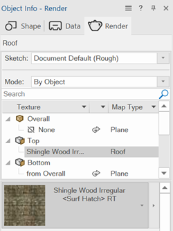
From the Render tab of the Object Info palette, add a texture to the top portion of the roof, such as Shingle Wood Irregular.
Our concept house is complete!
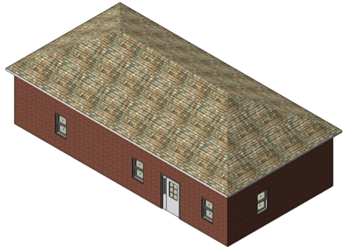
Use the Onscreen View Control cube or the Flyover tool  to look at the house from different angles. Optionally, you can switch to Design Layer-1 from the Active Layer list, and set the layer options to Active Only or Gray Others to be see the interior of the house with the roof hidden or grayed out. You could also hide Design Layer-2 from the Navigation palette.
