Quick Start: Let's set the stage
Difficulty level: Beginner
With a few clicks, you can get started in Vectorworks to set a simple stage and add some lights. Use this topic to help you understand how to create a stage, add a truss and lights, and focus the lights on the stage. The drawing we are creating is just a simple representation of a stage and is a good way to get started designing for events.

The location of commands and tools varies, depending on the workspace. You can learn to use the Quick Search feature to quickly find commands or tools; see Quick Search. You can also look at the Commands and tools PDF here in the Vectorworks help system.
Create a room
There are several ways to begin designing an event. We are starting by creating a room that represents the venue:
Select New to open a new, blank file.
The drawing opens in Top/Plan (2D) view.
Click the Rectangle tool  . Click to set the start point; move the cursor until you reach the desired room dimensions, such as 100' x 60' (30.48 m x 18.29 m). Click again to set the rectangle.
The rectangle's dimensions can be edited, if necessary, by selecting it and making changes in the Object Info palette.
With the rectangle selected, select the Create Room command.
Specify the wall and floor slab properties and attributes in the Create Room dialog box. Make sure to set an adequate height for the room, such as 25' (7.6 m).
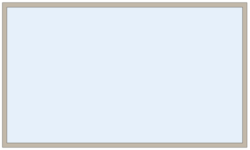
You should see four walls and a slab in a rectangular shape
On the View bar, select Right Isometric, from the Current View/Standard Views list to see the room in 3D view, or just press 3 on your numeric keypad or use the Onscreen View Control cube. You can switch back and forth between 2D and 3D views by pressing 0 or 3.
Four walls and a blue carpet floor
Set the stage
Click the Rectangle tool. Click to set the start point; move the cursor until you reach the desired stage dimensions, such as 50' x 15' (15.24 m x 4.57 m). Click again to set the rectangle.
With the rectangle selected, select the Create Stage command.
Set the stage height to 5' (1.5 m), and specify the stage properties and attributes in the Create Stage dialog box.
We now have a stage (one wall was removed for this representation)
Stage decks are inserted with rectangular areas. Other shapes might result in a combination of stage deck and/or stage plug objects.
Add a drape
A drape can make your stage look more professional. Let's place a drape around the stage. Click the Soft Goods tool  . Select a drape style from the Soft Goods Style Resource Selector, such as SG Stage Header.
Click to set the soft goods object's start point. Click to set the end of the segment and the beginning of the next. Continue drawing segments in this manner until the curtain object is complete, and then double-click. Make sure to set the drape height the same height as the stage, which is 5' (1.5 m) in our example.
A black drape was added
Add stairs
Your stage should have an entrance and an exit. Click the Stage Steps tool  . Place the stairs in the center of right side of the stage. Rotate the stairs to align with the stage, and click again to place. Repeat this step for the other side.
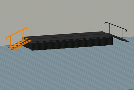
Stage and stairs with rails on both sides
Set the stage height to 5' (1.5 m), and specify the stage steps properties and attributes in the Stage Steps dialog box.
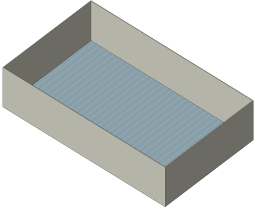
Add trusses
Next, we'll add a truss that we need to hang the lights. Click the Truss tool  .
.
From the Tool bar, click the Truss symbol list, and select a resource from the Resource Selector, such as the Eurotruss FD44 straight truss. Either double-click, or click Select, to choose the truss symbol. Click Distributed Insertion mode  .
.
In Top/Plan view, click once near the front corner of the stage, and click again at the other front corner, to place the truss along the stage line. In the Object Info Palette, enter a Z height of 20' (6.1 m) to change the height of the truss from the floor up.
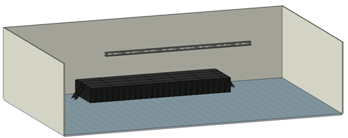
3D view of straight truss 20' (6.1 m) from the floor
Add lights
Let's add some lights. Click the Lighting Device tool  .
.
From the Tool bar, click the Lighting Device Symbol list, and select a resource from the Resource Selector. Either double-click, or click Select, to choose the lighting device symbol. For example, select USITT 4BS30 from the Lighting Instruments.vwx resources.
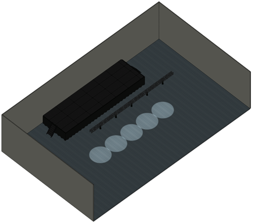
Click Distributed Insertion mode from the Tool bar, and enter 5 in Lighting Devices to Insert. Move the mouse to hover over the existing truss until valid connections are highlighted, and use the preview of the light to orient the lighting device. Click to insert the first lighting device, and move the mouse along the truss system. Click again to place five lights on the trusses.

Lights added to the truss
You could also place one light, select it, and then use the Align and Distribute tool. See Aligning and distributing objects for more information.
Press 3 on the numeric keyboard to return to right isometric view.
We have lights
Focus the lights
Notice the lights are facing down. We need to have them focused on the stage. In Top/Plan view, click the Focus Point tool  . Click an area on the stage where you would like the light to shine. Set the focus point height, such as 5' (1.5m), in the Place Focus Point dialog box. Repeat for the areas of the stage you want to light up, up to one focus point per light. The first focus point inserted is automatically named (A). You can change change the name; however, focus points inserted after this automatically continue through the alphabet and use the same focus point height entered for the first focus point.
Select a light to assign a focus point using the Selection tool. Click in Focus field of the Object Info palette and type in the name of the focus point. Repeat for all of the lights.
Light up the stage