 LED wall settings
These settings are available in the following locations:
LED Wall Preferences dialog box (creating an object)
LED Wall Settings dialog box (editing an object)
Object Info palette (editing an object)
LED Wall Style dialog box (creating or editing a style)
If a style is selected, only parameters set by instance can be edited (see Concept: Plug-in object styles). Parameters available only on the Object Info palette are listed at the bottom.
LED Wall settings: Overall
Click to show/hide the parameters.Click to show/hide the parameters.
|
Parameter |
Description |
|
Use Style |
From the Resource Selector, double-click a resource to activate it, or click Unstyled to convert a styled object to unstyled |
|
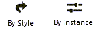
By Style/Instance |
A graphic indicates whether each parameter is set to By Style and given a fixed value or set to By Instance and editable in the dialog box. An object style may have a combination of both settings, to balance the need for consistency and flexibility. By Style/Instance settings are established by the style and cannot be changed from the settings dialog box.
To edit the object style, see Editing plug-in object styles; editing the style modifies all plug-in objects in the file that use the style. |
|
Preview |
Dynamically displays a preview of the LED wall, depending on the current pane |
|
View |
Select the standard view for the preview of the LED wall |
|
Render Mode |
Select the render mode for the preview of the LED wall |
|
Update Preview |
Updates the LED wall preview with the latest edits |
LED Wall settings: Design/Layout pane
Click to show/hide the parameters.Click to show/hide the parameters.
|
Parameter |
Description |
|
Wall Design/Drawing Settings |
The selections made here are reflected in the Tool bar when exiting the dialog box, and vice versa |
|
Wall Mode |
Selects the type of drawing mode |
|
Aspect Width/Height (Aspect mode) |
Sets the aspect ratio by entering a width and height value |
|
Aspect Tolerance (%) (Aspect mode) |
To allow flexibility when drawing LED walls within a specified aspect ratio, sets a tolerance percentage that allows panels to be placed beyond the aspect ratio boundary |
|
Builder Columns/Rows (Builder mode) |
Sets the number of rows and columns of panels to create on the LED wall |
|
Wall Height |
Displays the height of the LED wall based on the current parameter settings |
|
Maximum Wall Height |
Specifies the maximum height of the LED wall |
|
Wall Thickness |
Displays the thickness of a wall drawn without panels |
|
Total Wall Specifications |
Displays the LED wall specifications based on the current settings |
LED Wall settings: Panels pane
The main panel is usually the largest available and forms the main middle area structure, but you can optionally select multiple perimeter panels with a designated priority and placement position. The panel spacing, columns, and rows are all associated; changing one changes the others. When panel spacing is specified, the space between the columns and rows is accounted for in the overall size of the LED wall.
The Preview shows a simplified view of the panel placement as panels are selected.
Only main panels are available in Building mode; perimeter panels cannot be selected.
Click to show/hide the parameters.Click to show/hide the parameters.
|
Parameter |
Description |
|
Panel Positions |
Select the main panel type, and, optionally, select and position the perimeter panels |
|
Main Panel |
Click the Main Panel selector to select a resource from the Resource Selector |
|
Perimeter Panels |
Perimeter panels are usually smaller than the main panels, and serve to fill in the wall, or expand the wall to an unavailable size, when the LED wall needs to be larger than the main panels' available sizes |
|
Panel Symbol list |
Build the perimeter by selecting the panel, specifying each panel's position, and clicking Add |
|
Select Symbol |
Click the Perimeter Panels selector to select a resource from the Resource Selector |
|
Set Position |
Indicate where the selected panel should be placed by clicking on the appropriate location |
|
Add |
Adds the selected perimeter panel to the Panel Symbol list, at the selected position |
|
Delete |
Deletes the selected permiter panel from the Panel Symbol list |
|
Panel Spacing |
Adds space between columns and/or rows of panels; set the width |
|
Ignore hanging/stacking limits |
Allows walls to be built beyond the limits specified by selected panels |
|
Panel Specifications |
Displays the main panel or highlighted perimeter panel specifications (depending upon which one is selected), based on the current settings |
LED Wall settings: Visualization pane
You can adjust the LED wall intensity and glow by by editing the texture from the Resource Manager. See Editing textures and shaders from the Resource Manager.
Click to show/hide the parameters.Click to show/hide the parameters.
|
Parameter |
Description |
|
Image Settings |
|
|
Overall Texture |
Select the texture from the Resource Selector for the LED wall and panel exterior portions |
|
Image Adjustments |
|
|
Screen Image |
Select the screen image from the Resource Selector |
|
Symmetrical Pixel Pitch |
Sets the same distance between pixel pitch in the horizontal and vertical directions |
|
Pixel Pitch X/Pixel Pitch Y |
Sets the distance between pixel centers in the horizontal and vertical directions, indicating the density of pixels on the screen. Select Symmetrical Pixel Pitch to set the same distance in both directions. A smaller pitch value means a higher pixel density, and therefore, resolution. |
|
Scale (%) |
Enter a percentage to scale the image |
|
Rotation |
Rotates the image by the specified number of degrees |
|
Horizontal Shift (Pixels)/Vertical Shift (Pixels) |
Shifts the image horizontally to the left (negative value) or right (positive value) or vertically up (positive value) or down (negative value) |
|
Tile image |
Repeats the image over the screen; deselect to show a single instance of the image |
|
Enable Video |
Displays the selected video on the LED wall |
|
Video Source |
Select the video source; the source can consist of either a video file or a capture device |
|
File |
|
|
Video Filename |
Displays the name of the selected video file |
|
Select File |
Browse to select a video file for display |
|
Capture device |
|
|
Capture Source Name |
Identifies the external video capture source with a reference name |
|
Capture Source Number |
Enter the number for the capture source |
|
Retain mapped panel image |
When moving or changing internal panels within a wall, preserves the original image on the edited panel as it was originally specified |
|
Total Wall Specifications |
Displays the LED wall specifications based on the current settings |
LED Wall settings: Data/Power/Numbering pane
Select how to autonumber the LED wall circuits, sections, units, and power. See Numbering Spotlight objects. The Preview area is zoomed in so you can verify the numbering pattern.
Select the option to Enable internal auto-numbering if you want all panel numbering to be automatically re-numbered after making a manual edit. When the option is deselected, manual edits to panel numbering do not affect other panel numbers.
After placing the LED wall, specify the Power Information from the Object Info palette as described below.
LED Wall settings: Classes/Attributes pane
Click to show/hide the parameters.Click to show/hide the parameters.
|
Parameter |
Description |
|
Lines and Curves |
When drawing panels with straight lines combined with curved segments, these default settings force the wall to be drawn within certain parameter ranges. Concave and convex refer to the front-facing wall curvature. |
|
Use panel and curve increments |
Facets the panel as it is placed along a curve; deselect the option for a smoothly curved wall (however, this means you cannot set angular limits when drawing the wall) |
|
Panel Width |
Sets the distance between the Joint Max locations, also known as the distance between each snap point along the linear path of straight and curved lines. If you can't locate a particular brand of LED symbols, you can use this setting to correspond to panel widths from, for example, a rental supply company. |
|
Panel Bend Points |
Specifies the number of bend points (hinge points) on each panel, dictating the smoothness of the final curved face. A panel bend point of 0 anchors the change of direction at the ends of the panel, for static curved and flat panels. A setting of 2 splits the panel in half, allowing a change in direction at the midpoint for creating S-curved panels; infinite bend points allow you to click as many times as needed to change directions. This setting also allows you to mimic a wall with panels when no panel symbols have been selected. |
|
Concave Degrees / Convex Degrees |
Forces curved lines to follow limits of +/- the degree value in the concave and/or convex direction |
|
Concave Joint Max Degrees / Convex Joint Max Degrees |
Sets the maximum allowable degree of concave or convex curvature at the joint angle, specifying how much an LED wall can curve. Flat panels should have both values set to 0. Static curved panels should have one value set to a positive angle, and the other set to the opposite of that angle (for example, concave set to 20 and convex set to -20). Curvable panels are able to curve between the maximum limits set; both fields shoud be positive (or one can be set to 0) for panels that can bend only in one direction. |
|
Facet curves |
When selected, curves are not smooth but are segmented; deselect the option for smooth curves |
|
Class Assignments |
Specify class naming for the various portions of the LED wall. This allows portions of the wall to be set to visible, grayed, or invisible. Use the standard class, select a class from the list of classes present in the drawing, or create a new class. Class Prefix: Specifies an optional default root class naming standard for all LED wall parts; click Assign Default Classes With Prefix to begin all wall class names with the prefix, so that they are sorted together. Assign Default Classes With Prefix: Sets the class names for all LED wall elements to the standard, using the Class Prefix if there is one. LED Wall elements: For each portion of the LED wall, specifies the class name standard; the class names shown here are applied to the elements. |
LED Wall settings: Data Tags pane
Assign data tags to the LED wall, and also to the panels and accessories (supports).
Click to show/hide the parameters.Click to show/hide the parameters.
|
Parameter |
Description |
|
LED Wall Data Tags |
|
|
Data Tag list |
Lists the data tag symbols that apply to the LED wall; select the tag, specify each tag's view and position, and click Add |
|
Select Data Tag |
Click the Data Tag selector to select a resource from the Resource Selector |
|
Tag View |
Specify the direction for the tag |
|
Position |
Indicate where the selected tag should be placed in relation to the LED wall by clicking on the appropriate location |
|
Add |
Adds the selected data tag to the LED wall data tag list, at the selected position |
|
Delete |
Deletes the selected data tag from the list |
|
Panel and Accessories Data Tags |
|
|
Panel and Accessory Data Tag list |
Lists the data tag symbols that apply to the panels and/or accessories (top bar or bottom bar) |
|
Select Data Tag |
Click the Data Tag selector to select a resource from the Resource Selector |
|
Object |
Select the object for the data tag |
|
Tag View |
Specify the direction for the tag |
|
Position |
Indicate where the selected tag should be placed in relation to the LED wall by clicking on the appropriate location |
|
Add |
Adds the selected data tag to the panel and accessories data tag list, at the selected position |
|
Delete |
Deletes the selected data tag from the list |
LED Wall settings: Wall Support pane
LED walls can be hung from above (top bar supports) or supported from the ground (base bar). These are considered LED accessories. Both types of supports are available in single, double, and triple sizes.
Top support symbols can be converted to truss-like objects with the Convert to Truss command, allowing users to attach hoists, cable drops, slings, etc., between the top bar and a supporting truss above.
Click to show/hide the parameters.Click to show/hide the parameters.
|
Parameter |
Description |
|
Support Structure |
Indicates whether the LED wall has top or ground supports |
|
Top support |
Select the option to include a top support for the wall (top support symbols need to be present in the Support Symbols list to be able to select this option, if a bottom support is already selected) |
|
Ground support |
Select the option to include ground support for the wall (bottom support symbols need to be present in the Support Symbols list to be able to select this option, if a top support is already selected) |
|
Offset Vertical Distance |
Offsets the wall vertically from its insertion point. When supports are selected, you cannot specify an Offset Vertical Distance. |
|
Support Symbols |
|
|
Support Symbols list |
Lists the support symbols that are applied to the LED wall |
|
Select Symbol |
Click the Select Symbol selector to select a resource from the Resource Selector |
|
Add |
Adds the selected support symbol to the Support Symbols list |
|
Delete |
Deletes the selected support symbol from the list |
|
Highlighted Support Specifications |
Displays the highlighted support's specifications based on the current settings |
LED Wall settings: Object Info palette
These options are only available from the Object Info palette for a selected object.
If you have rearranged the geometry, added new panels, or deleted existing ones, and then you edit the wall geometry further in a way that affects the panels or accessories that were manually rearranged or edited, you'll be warned that your manual edits might be lost. The LED wall is reconfigured based on the new settings selected in the LED Wall Settings dialog box.
Click to show/hide the parameters.Click to show/hide the parameters.
|
Parameter |
Description |
|
Style |
Replace, edit, or remove the current style, or (for unstyled objects only) create a new plug-in style (see Custom plug-in object styles without catalog options). Editing a style changes all instances in the file that use the style. |
|
Hide style parameters |
Hides the parameters that are set by style; these cannot be edited from the Object Info palette |
|
Wall Width/Wall Height |
Specifies the wall's width and height values; these values are linked for aspect walls |
|
Top Trim/Bottom Trim |
The top trim is the elevation of the top of the wall; the bottom trim is the top trim minus the wall height. Changing the bottom trim can affect the overall wall height. Wall height changes when there supporting structures affect the trim values. Adding hanging supports means that wall height changes affect the bottom trim; adding ground supports means that wall height changes affect the top trim. |
|
Settings |
Opens the LED Wall Settings dialog box, to edit the parameters of the selected LED wall |
|
Wall ID/Location/Position/Unit/Purpose/Notes |
Adds information which can be placed on the drawing or used for reporting |
|
Select Video Source File |
When the video source is a file, the file name displays in Video Source File. Click Select Video Source File to select a different video file. |
|
Create Worksheet Report |
Generates a detailed worksheet that reports on the LED wall's size, part requirements, video pixel resolution, and more, to facilitate communication with event staff and equipment suppliers |
|
Load Information |
An LED wall is considered a distributed load in Braceworks calculations; if the wall is inserted parallel to a rigging object, it is considered to be a load on that structure. Load information is used for Braceworks calculations and reports (Braceworks required). |
|
Include in calculations (Braceworks required) |
Includes the LED wall in Braceworks calculations; deselect to exclude the object from participating in structural calculations |
|
Load Group Name |
The load category is always Video for LED wall objects |
|
Load ID |
Enter a unique ID for the load for informational use in reports |
|
Load Name |
Identifies the object in load calculations |
|
Distributed Weight |
Enter the distributed weight of the LED wall object; changes here also affect the Total Weight value |
|
Total Weight |
Enter the total weight of the object |
|
Position |
Displays the name of an associated rigging object, if the object is attached. For methods to attach loads, see Making the attachment. |
|
Power Information (panel symbols) |
LED walls with specified panels can assign the panels in the wall to the available power and data sources, and create a power schematic view as described in Concept: Power schematics |
|
Power/Data information |
Select the power and data sources from the lists of sources in the file; enter text in the search box to filter the list. The associated power information and connections from the selected source display, and a cable is automatically added from the source to the LED wall. |
|
Select Power Source |
Selects the connected input source of power for the LED wall in the drawing area; see Tracing a power source to its origin for how to trace a power source through sequential objects |
|
Equipment Subparts |
Lists the subparts that make up the object. These subparts are counted and reported separately in equipment and inventory lists. The parameters must be selected for display for this type of object in Spotlight preferences: Inventory pane. |
|
Equipment Virtual Parts |
Virtual parts are associated with an object and are reported in equipment and inventory lists, but do not display in the drawing. After adding virtual parts, they are listed in the Object Info palette. |
|
Edit Virtual Parts |
Opens the Virtual Parts dialog box to add virtual parts to the object; see Managing virtual parts and independent virtual parts |
|
Assign Sources |
Opens the Assign Sources dialog box to assign the object and its subparts and virtual parts to an inventory source; see Assigning equipment to an inventory |
![]()