 Existing tree settings
These settings are available in the following locations:
Existing Tree Preferences dialog box (creating an object or importing a tree survey file)
Existing Tree Settings dialog box (editing an object)
Object Info palette (editing an object)
Existing tree settings: General pane
Click to show/hide the parameters.Click to show/hide the parameters.
|
Parameter |
Description |
|
Botanical Name/ Common Name |
Enter the tree’s botanical and common name; alternatively, click Get Species Data to use the plant database (legacy) |
|
Get Species Data |
Opens the Species Data dialog box, to select a tree species from the list; see Specifying existing tree species information |
|
Family |
|
|
Origin |
Specifies whether the tree is an endemic, native, exotic, or indigenous species, or select Custom and specify a Custom Origin type |
|
Invasive |
Indicates that the species is invasive |
|
Numbering Options |
|
|
Tree ID Number |
Displays the tree’s autonumber, when autonumbering is enabled. When importing from a tree survey, map the tree ID to this parameter. |
|
Auto number this tree |
Enables tree autonumbering |
|
Tree number |
Select whether to manually enter a name for this instance or to use a name formula. For Manual, enter a name. When displaying transplanted trees, for example, the same number is needed for the tree representation in the original and new locations. For one of the representations, manually number the tree and enter the identical number. For Instance name formula, select a name formula from the list of name formulas present in the drawing. Select Manage Custom Name Formulas to add, edit, or delete a name formula from the list; see below. Instance name formulas can only be applied when autonumbering a tree at placement, so they are only available from the Preferences dialog box. |
|
Tag (Legacy) |
Sets up an internal tag for existing trees; using a data tag instead is recommended |
|
Tag Options (Legacy) |
Opens the Tag Options (Legacy) dialog box, if you want to use the legacy plant ID tag. Use existing tree tag: Labels the exisiting trees with the options specified Snap tag to edge of trunk: Snaps the end of the leader line to the edge of the trunk; deselect to adjust the endpoint location manually Display marker at the end of the tag leader: Adds a marker to the leader line endpoint. The marker style is controlled by the ID tag class. Enable tag shoulder line: Adds a shoulder to the leader line Shoulder Angle: Sets the angle of the ID text and shoulder Display: Specifies the information to display in the tag; each item displays on its own line. The Notes information is set from the Object Info palette. Class: To control appearance and visibility, select a class from the list of classes present in the drawing Apply to: Select how to apply the tag |
Adding or editing an instance name formula
To create or edit a name formula for an existing tree instance:
On the General pane of the Existing Tree Preferences dialog box, select Instance name formula for the Instance Name.
In the list of name formulas, select Manage Custom Name Formulas to open the Manage Custom Name Formulas dialog box.
Click Add, or select a name formula from the list and click Edit.
To delete a name formula from the list, select it and click Delete.
The Add/Edit Custom Name Formula dialog box opens.
Click to show/hide the parameters.Click to show/hide the parameters.
|
Parameter |
Description |
|
Name |
Enter the formula's display name, for use in the list of name formulas |
|
Name Definition |
Displays the name formula, which can consist of selected name components and manually entered characters |
|
Name Component |
To add a name component to the name formula, select it from the list, and then click Add. The component is added to the end of the Name Definition. |
|
Start Value/Increment/ Leading Zeroes |
If Incrementing Value is selected for the Name Component, before clicking Add, enter the Start Value, Increment, and Leading Zeroes. These are added to the formula. |
Existing tree settings: Size and Root Zone pane
Click to show/hide the parameters.Click to show/hide the parameters.
|
Parameter |
Description |
|
Size |
|
|
Height |
Sets the height of the tree |
|
Canopy Diameter (regular canopy shape) |
Sets the tree’s canopy diameter, for a regular shaped canopy |
|
Irregular Canopy Size |
Trees are not always perfectly symmetrical; this opens the Irregular Canopy Size dialog box to specify the plan shape of an irregular canopy rather than use the regular canopy diameter method. Select Use canopy offsets from center of trunk and define the measurements, in the cardinal directions, from the center of the trunk to the edge of the canopy. To set the irregular canopy distances in eight directions, select Add intercardinal directions. |
|
Canopy Area |
Displays the calculated area of the tree canopy |
|
Crown Clearance |
Specifies the distance from the ground to the start of the crown; this parameter determines the crown's 3D geometry and its bottom position |
|
First Branch Height |
Indicates the height of the lowest (first) branch |
|
First Branch Direction |
Select the cardinal direction of the first branch |
|
DBH |
Specifies the diameter of the tree trunk at breast height. Adult breast height is considered to be 51–55” (1.3–1.4 m) above the ground. The DBH value also determines the initial diameter of the critical and primary root zones. The DBH is used in Biodiversity Net Gain (BNG) calculations for the Sustainability Dashboard. The trunk perimeter is calculated from the DBH. Trunk perimeter = DBH X A tree with multiple stems displays with the number of stems after the DBH value, which cannot be edited. Because this kind of tree does not have a single central trunk, the DBH is calculated differently, by calculating the square root of the sum of each stem’s squared diameter value. |
|
Opens the Multiple Stem Calculator dialog box, for trees with more than one central trunk or stem. Select Use Multiple Stems, and then specify the diameter of each stem or trunk to include in the DBH calculation. The DBH is automatically calculated, but can be adjusted if necessary. |
|
|
Root Zone |
|
|
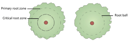
Root Display |
Sets whether to display the critical and/or primary root zones, the root ball zone only, or no root zones. Specify the appearance of the zones in the 2D Properties.
|
|
Critical Root Diameter |
Specifies the diameter of the critical root zone; initially, this value is set to 2.5 times the DBH, but the value can be changed. A changed value is reset if the Root Display is turned off; set the value to 0 (zero) to re-apply the DBH factor. |
|
Primary Root Diameter |
Specifies the diameter of the primary root zone; initially, this value is set to 5 times the DBH, but the value can be changed. A changed value is reset if the Root Display is turned off; set the value to 0 (zero) to re-apply the DBH factor. |
|
Ball Diameter |
When the root ball is set to display, indicates the diameter of the root ball |
|
Tree Protection Zone |
Select how to display the area around the tree that protects the tree. Select a circular zone and enter the TPZ Radius. Select 12 x DBH, a circular tree protection zone that is calculated based on 12 times the diameter at breast height (DBH) parameter. Select None to not display a tree protection zone. You can also create a 3D tree protection zone that acts as a grade limit with the nearest site model; see Creating 3D tree protection zones. |
|
TPZ Radius (circular zones) |
For a circular protection zones, displays the radius of the zone |
|
TPZ Area |
Displays the calculated area of the tree protection zone; the original area displays even if the TPZ is edited later |
|
Edit tree protection zone |
Adjusts the shape of the TPZ; see Specifying the tree protection zone |
|
TPZ Corner Radius |
When the tree protection zone editing mode is enabled, specifies the corner radius of the protection zone; set to a smaller value to simulate sharp corners |
|
Adjusted TPZ Area |
If the TPZ was manually adjusted by selecting Edit tree protection zone, displays the adjusted area |
|
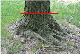
Display buttress and Structural Root Zone (SRZ) |
The buttress is the location on the trunk immediately above the base of the tree where the trunk mostly becomes parallel, as shown by the red line in this example:
The Structural Root Zone (SRZ) refers to the circular area around the base of a tree that is required for the structural stability of the tree. The appearance of the SRZ indicator is set from the Attributes pane. |
|
Diameter at Buttress |
Enter the trunk diameter at the buttress |
|
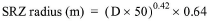
Minimum SRZ Radius |
Displays the structural root zone radius value in meters, which is calculated based on the diameter at buttress value (D) according to the following formula:
If the calculated value is less than the Minimum SRZ radius specified, the minimum value is displayed instead. |
|
Calculated SRZ Radius |
Displays the calculated SRZ radius |

Existing tree settings: Additional Data pane
Click to show/hide the parameters.Click to show/hide the parameters.
|
Parameter |
Description |
|
Existing Tree Protection Order (TPO) |
Select if the tree has an existing TPO |
|
Condition |
Indicates the condition of the tree: excellent, good, average, poor, or custom |
|
Custom Condition |
When a custom condition is selected, enter the custom tree condition |
|
SULE |
Indicates the Safe Useful Life Expectancy (SULE) rating for the tree. A custom life expectancy value can be entered. |
|
Custom SULE |
When a custom SULE is selected, enter the custom life expectancy |
|
Category |
Specifies the category of the existing tree. This selection is related to the category color set in the 2D Properties dialog box. A custom category can be set. |
|
Custom Category |
When a custom category is selected, enter the custom tree category. To preserve the ability to set and display the category color even with a custom category, select one of the provided category values, and then select its Action. Then select Custom for the Category. Keep the initial default category word, and then enter any custom information. For example, to use the Hazardous category, but add custom comments, select Hazardous, an Action of Remove, and then Custom. After the word Hazardous, add your custom comment, such as "Hazardous - remove immediately." By retaining the word Hazardous at the start of the custom comment, the category color selected for Hazardous still displays. |
|
Action/Comment |
Indicates the action to be taken for the tree. The category selected (Retain, Transplant, or Remove) determines the symbol to display based on the selections made in the 2D Properties dialog box. A custom action can be set. When transplanting a tree, set the original tree Action to Transplant - Original location. Copy the tree, disabling its automatic numbering properties and manually assigning it to the same Tree No. as the original tree. Move the copy to the new tree location and set the Action for the copy to Transplant - Proposed location. |
|
Custom Action/Comment |
When a custom action is selected, enter the custom action to take for the tree. To preserve the ability to automatically set the displayed symbol, select one of the provided actions, and then select Custom. Keep the initial default action category, and then enter any custom information. For example, to use the Remove category, but add custom comments, select Remove, and then Custom. After the word Remove, add your custom comment, such as "Remove - storm damaged." By retaining the word Remove at the start of the custom comment, the symbol selected for Remove still displays. |
|
Reduced Level/Age/Year Planted/Date Assessed/Location/Notes |
These parameters provide additional information about the tree and can be included in reports and in any data tags. Notes can be selected for display in the tree tag (legacy). The field names can be edited, and additional fields can be added, by clicking Additional Fields. |
|
Veteran tree/Ancient tree |
Indicates that the tree is special due to its age |
|
Form |
This refers to the shape of the tree, from uniform (excellent) to lopsided (poor) |
|
Structure |
Trees with excellent structural integrity, growing in native habitat, rate higher than less stable trees or trees not growing in typical habitat for the tree type |
|
Vigor |
This describes the health of the tree and whether it is growing well, with no pests and with good structure and form |
|
Opens the Additional Fields dialog box, for customizing Object Info palette fields, adding custom fields, and including arborist parameters in worksheet reports. The first six default fields from the Object Info palette can be edited to use different field names, and four additional fields can be named. You can add default values. To edit the field label or value, click on the name and type in the new value. Choose how many objects to affect by selecting an option from the Apply the above field names to list. Select how many of the fields to display in the Object Info palette. Even if fields do not display, the parameters can still be used in worksheets (use the worksheet formula =(“Existing Tree”.“Fieldx”) where x is the field number to report on these fields). |
Existing tree settings: Sustainability pane
The sustainability pane allows you to attach one or more sustainability frameworks to the object. You can attach and specify frameworks and then save the object as a styled object, saving time. Each object's specific parameters can be edited later from the Data pane of the Object Info palette.
For more information on sustainability frameworks and associated parameters, see The Sustainability Dashboard.
To attach and specify a sustainability framework:
Click <New Framework> to select a framework to attach from the Selected Framework list.
Click Edit Framework to specify the sustainability parameters for that framework.
The available options depend on the selected framework. The options that are not part of the Sustainability Dashboard are described in the table below.
The framework's parameters affect the associated sustainability framework calculations, if applicable, as objects are placed in the drawing. View the results in the Sustainability Dashboard.
Click to show/hide the parameters.Click to show/hide the parameters.
|
Parameter |
Description |
|
Frameworks list |
Lists the frameworks attached to the object. Click <New Framework> to attach a framework. |
|
Selected Framework |
|
|
Framework |
Lists the available frameworks and metrics. Many of these frameworks are associated with metrics on the Sustainability Dashboard; the others are described below. |
|
Edit Framework |
Opens an editing dialog box to specify sustainability parameters for the object |
|
Delete Framework |
Deletes the selected framework from the object |
|
Frameworks not currently part of the Sustainability Dashboard |
|
|
Permeable Surface |
|
|
Permeable Surface |
Select whether the object is permeable or non-permeable. If it is permeable, enter the Rate, and select the units. |
|
Runoff Coeff |
Enter the runoff coefficient |
|
Solar Reflectance Index (SRI) |
Enter the solar reflectance index value |
Existing tree settings: 2D Properties pane
The 2D Properties pane controls the symbol for the tree and trunk, and also sets the appearance of retained, removed, or transplanted trees, as well as category colors to indicate the tree's relative importance.
The appearance depends on whether you use action-based attributes; certain 2D properties depend on selections made from the Object Info palette for each existing tree, and are not applied immediately. For example, the symbol specified in Tree Remove does not display unless Remove is selected as the Action for the tree.
The 2D canopy attributes and the trunk pen line are set from the Attributes palette as long as the action-based settings are deactivated. Even if you don't use action-based attributes, the trunk symbol changes depending on the set action. When you set the attributes to be steered by action, this overrides any class-based attributes, and the Attributes palette no longer affects the appearance.
The hierarchy for applying attributes, and the ultimate appearance of the 2D tree, depends on the selections made:
No 2D action-based symbols: Existing tree attributes are determined by the Attributes palette and/or class attributes.
2D action-based symbols specified: The action-based appearance overrides the Attributes palette and/or the class attributes.
Category applied, with canopy fill: The category appearance overrides the Attributes palette, class attributes, and the 2D action symbol for fill color.
The symbols for retained and removed trees are scaled by the canopy height and diameter specified from the Object Info palette. The original and proposed symbols for a transplanted tree are scaled by the DBH parameter. If the tree has an irregular canopy, not all symbols are available.
Click to show/hide the parameters.Click to show/hide the parameters.
|
Parameter |
Description |
|
Use action-based 2D symbols |
Uses 2D symbol components to display the tree. The tree symbol displayed in the drawing depends on the Action specified from the Object Info palette. |
|
Tree Retain |
Select the symbol to display for a tree that is retained (the associated Object Info palette Action is Retain) |
|
Tree Remove |
Select the symbol to display for a tree to be removed (the associated Object Info palette Action is Remove) |
|
Custom Action |
Select the symbol to display for a tree with a custom action (the associated Object Info palette Action is Custom) |
|
Trunk |
Select the tree trunk symbol for either retained or removed trees |
|
Use additional X marker for remove trees |
In addition to the selected symbol for removed trees, adds an X to indicate that the tree is to be removed |
|
Transplanted Trees |
If a tree is to be moved from one location to another, select the symbol to display for the existing position of a tree to be transplanted (the associated Object Info palette Action is Transplant - Original location); select the symbol to display for the new position of the transplanted tree (the associated Object Info palette Action is Transplant - Proposed Location). Specify the tree trunk symbol for transplanted trees in both the original and new locations. |
|
Use category colors |
Applies category colors to the tree to indicate its relative importance on the site. The Category color used depends on the Category selected from the Object Info palette. |
|
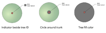
Display |
Selects the type of display for the category colors. Setting the display to Tree fill color overrides any class-based attributes.
Use the category color as a tree fill for complex plans with multiple trees, to easily distinguish categories for densely forested areas. |
|
Use as document defaults |
Applies the properties to the currently selected existing tree and sets the properties as the default preferences for the Existing Tree tool. Existing trees placed by the tool after clicking OK will have these properties applied. |
Existing tree settings: 3D Properties pane
The 3D appearance controls the symbol for the canopy and trunk in 3D views.
Click to show/hide the parameters.Click to show/hide the parameters.
|
Parameter |
Description |
|
Create 3D geometry |
Creates 3D geometry for the existing tree |
|
3D Geometry Type |
Select the type of geometry to use for the 3D appearance of the tree. Three choices allow you to select the best representation for the design's stage and needs. |
|
Generated |
The 3D canopy shape is affected by changes in the Object Info palette for height, diameter, irregular canopy shape, Crown Clearance, and DBH values. This is the best 3D representation for irregular canopies. Textures for the generated 3D canopy and trunk are set in the Attributes pane. |
|
Canopy Shape |
Select the symbol to display for the 3D canopy |
|
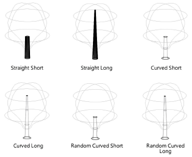
Trunk Shape |
Select the symbol to display for the 3D trunk shape. Short trunks extend to the Crown Clearance value, while long trunks extend into the canopy. If using a canopy texture that is partially transparent, use a long trunk shape for a more realistic appearance. A curved shape gives the trunk a flanged appearance near the ground; random selections are slightly more free-form in shape.
|
|
Maxon plant |
|
|
Select a tree representation from the Maxon Plant library |
Click Maxon Asset Catalog to select a Maxon tree to use for the 3D geometry; see Adding 3D plants from Maxon Plant |
|
Image prop/3D symbol |
|
|
Create from Resource |
Select an image resource (for an image prop) or a 3D symbol from the Resource Selector. The overall spread and height from the settings affect the appearance of the image, but the image cannot represent specific parameters like an irregular canopy or crown clearance. Image props can be used as 3D tree geometry. However, canopy height and canopy diameter changes do not affect the geometry of image props. |
|
Use as document defaults |
Applies the properties to the currently selected existing tree and sets the properties as the default preferences for the Existing Tree tool. Existing trees placed by the tool after clicking OK will have these properties applied. |
Existing tree settings: Attributes pane
Click to show/hide the parameters.Click to show/hide the parameters.
|
Parameter |
Description |
|
Attributes list |
Lists all geometry that has graphic attributes settings. The class and graphic attributes of each part of the object are displayed. Depending on action-based settings, some attributes may be overridden. Select a row in the list and click in a cell to do any of the following: To control appearance and visibility, select a class from the list of classes present in the drawing, or create a new class. Select <Existing Tree Class> (or <Exist Tree-3D Canopy>, or <Exist Tree-3D Trunk>) to place the part in the same class as the object. Set the attributes; see The Attributes palette. To specify a texture for a 3D part, select a texture from the Resource Selector, or click one of the buttons to use no texture, or to use the class texture. Set the map type and rotation as needed; see Concept: Texture projection and orientation. |
|
Make All Attributes by Class |
Sets all fill, pen, line, and texture attributes by class; this option is not available from the preferences when the active class is set to Use at creation |
|
Remove All by Class Settings |
Removes all by class settings for fill, pen, line, and texture attributes; this option is not available from the preferences when the active class is set to Use at creation |
Object Info palette
Most parameters are described in the panes above. Only the parameters that are different in the Object Info palette are described here.
Click to show/hide the parameters.Click to show/hide the parameters.
|
Parameter |
Description |
|
Z |
Indicates the elevation above the site model surface |
|
Existing Tree Settings |
Opens the Existing Tree Settings dialog box |
|
Elevation |
Indicates the layer elevation |
![]()