 Grade settings
These settings can be used to define a specific grade object's general and graphics settings, and to control direction indicator and analysis settings for all grade objects in the file. They are available in the following locations:
Grade Preferences dialog box (creating an object)
Grade Settings dialog box (editing an object)
Object Info palette (editing an object)
Grade settings: General pane
The settings on this pane apply to specific grade objects in the drawing.
Click to show/hide the parameters.Click to show/hide the parameters.
|
Parameter |
Description |
|
General |
Given two parameters, the grade parameters are calculated for the remaining parameters. Enter the two known parameters to calculate and display the other grade parameters. The initial elevation of the first and/or second points of the grade object is determined by these methods: If an existing grade object is under one of the points, the elevation of the existing grade object is used. If a stake object is under one of the points, its elevation is used. If a site model is under one of the points, the calculated elevation of the point is used. If none of the above occurs, the values of Parameter 1 and Parameter 2 are taken into account. |
|
Parameter 1 |
Select the first known parameter (Elevation 1, Elevation 2, Downward Grade in %, Upward Grade in %, Downward Ratio (rise/run), Upward Ratio (rise/run), or elevation change) and enter the value associated with the parameter |
|
Parameter 2 |
Select the second known parameter (available choices depend on the first parameter selected; at least one of the two known parameters must be an elevation), and enter the value associated with the parameter |
|
Parameter display |
The remaining parameters are calculated and displayed |
|
Site Model |
|
|
Grade Object Mode |
Use grade object height: Uses the elevation values specified in the General parameters. Use height from site model: When the grade is drawn over a site model, the elevation of the first and second points is derived from either the existing or proposed site model. The values in the General parameters do not apply. The grade object updates with the site model. Change site model (use grade as pad modifier): Uses the grade object as a site modifier object; the elevation values specified in the General parameters are applied to either the existing or proposed site model. Update the site model to apply the changes (select the site model and click Update from the Object Info palette). |
|
Site Model Layer |
To change the connected site model (see Connecting drawing objects to the site model), select the site model's design layer. The site model must be updated for the grade to modify it. If you want the grade to connect among different site models for a project with surveys that update throughout the stages of the design, or for testing different design solutions without needing to manually reconnect it every time, place the grade on a layer above the site model layers, and select Auto here; the grade will automatically connect with the visible site model that is closest below it in the stacking order. |
|
Apply To |
Select whether the existing or proposed site model provides elevation values when Use heights from site model is selected, or which site model to modify when Change site model is selected |
|
Simplification Tolerance |
For a curved grade serving as a site modifier, enter a positive value to redefine the horizontal distance between the closest parts of two neighboring portions of the modifier. A longer distance simplifies the modifier polygon, reducing the number of source points that modify the site model. A shorter distance increases the number of source points that modify the site model. A value of 0 (zero) doesn't simplify the modifier. |
Grade settings: Graphics pane
The settings on this pane set the graphic appearance of the grade object. The appearance of the indicator, grade definition, and precision for all grades in the file is set in the Direction Indicator pane.
Once created, each graphic element of the grade object has its own handle. Move a handle to adjust the position of the text and indicator.
Click to show/hide the parameters.Click to show/hide the parameters.
|
Parameter |
Description |
|
Elevation Points |
|
|
Elevation marker symbol |
Click the elevation marker symbol selector to select a resource from the Resource Selector. The marker appears at each end of the grade object. |
|
Scale |
Scales the elevation marker with respect to the layer scale by the specified scale factor; a Factor of less than one decreases the size of the marker while a Factor of more than one increases its size |
|
Data Tags for Elevation Points |
Lists the data tags assigned to the grade's elevation points, which are considered subparts of the grade, for data tag and reporting purposes. Multiple data tags can be selected to serve as labels for elevation points. See Creating data tag styles. To control the appearance of the data tags, edit the data tag style. You can also use the Data Tag tool to apply a tag to an elevation point; manually applied tags are not listed here. |
|
Visible |
Specifies whether the data tag is visibile in the drawing. You can also delete an individual tag from the drawing to make it invisible; the data tag style remains in the list. Change the setting here to make the tag visibile again. |
|
Add |
Opens the Choose Data Tag Style dialog box to select a data tag for the elevation point |
|
Replace |
Opens the Choose Data Tag Style dialog box to select a data tag to replace the selected tag |
|
Delete |
Removes the selected data tag from the list |
|
Slope and Line |
|
|
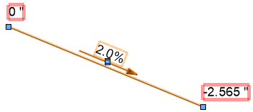
Show slope value |
Displays the grade value. If the value does not display, increase the text size by selecting Text > Size. |
|
Show projected/surface length value |
Displays the projected grade length/surface length and the slope arrow; the slope arrow always indicates the downward slope direction. Enter a prefix for the value, if desired. The projected length is the distance between the points as measured along a horizontal projection; the surface length is the distance between the points as measured along the surface, which facilitates a more accurate calculation for purchasing estimates. If both Show projected length value and Show surface length value are selected, both values are displayed along the grade object, with a slash (/) between them (prefix + projected length/prefix + surface length). |
|
Show length value(s) below arrow |
When Show projected length value and/or Show surface length value is selected, displays the value below the slope arrow |
|
Draw line |
Draws a slope line to represent the distance between the two elevation points |
Grade settings: Direction Indicator pane
The settings on this pane apply to all the grades in the file.
Click to show/hide the parameters.Click to show/hide the parameters.
|
Parameter |
Description |
|
Display |
|
|
Arrow Line Length |
Specifies the length of the grade directional arrow, in page units |
|
Arrow Offset |
Sets the distance of the grade directional arrow from the grade line, in page units |
|
Draw arrow parallel to curved grade object |
Draws curved arrow lines parallel to curves in the grade line; if deselected, all arrows are drawn straight |
|
Grade Definition |
Select the type of display for the slope (percent, permille, run/rise ratio, rise/run ratio, or angle) |
|
Precision |
Sets the displayed precision for the slope value |
|
Attributes |
|
|
Pen/Color/Style |
Select the pen style, color, and line thickness for the grade directional arrow. Alternatively, select Class style in the Pen list. The pen, color, style, and marker are then determined by the class attributes of the grade object. |
|
End Marker |
Specifies the marker type for the end of the grade directional arrow |
|
Opacity (%) |
Sets the opacity of the grade directional arrow; drag the slider to the left to decrease opacity, or enter an opacity percentage |
|
Use class opacity |
The opacity of the arrow can be set by the class of the grade object |
|
Make All Attributes by Class |
Sets all pen attributes by class |
|
Remove All by Class Settings |
Removes all by class settings for pen attributes |
Grade settings: Analysis pane
Grade objects can be used to analyze the slopes in a drawing. Grades that are outside specified slope or elevation ranges are considered critical, and are highlighted and/or selected, as specified. These settings apply to all the grades in the file.
Click to show/hide the parameters.Click to show/hide the parameters.
|
Parameter |
Description |
|
Mark Objects |
Select the action to take when critical grade objects are identified |
|
Highlight critical objects |
Click the color box to select the highlight color for grade objects that meet the criteria |
|
Select critical objects |
Select all grade objects that meet the criteria |
|
Criteria |
Specifies the criteria for critical grade objects |
|
Grade out of range (%) |
Sets a range of acceptable slope values; grades outside of the range are considered to be critical |
|
Elevations out of range |
Sets a range of acceptable elevation values; elevations outside of the range are considered to be critical |
|
Show intersections |
Specifies that any intersecting grade objects should be considered critical |
Grade settings: Object Info palette
Grade objects can be edited from the Object Info palette. Commonly-required parameters can be accessed directly from the Object Info palette, or click Settings to change any of the parameters of selected grade objects, or the global settings for all grade objects in the file. Parameters that are available in the dialog box are described in the tables above. Only the parameters that are different are described here.
Click to show/hide the parameters.Click to show/hide the parameters.
|
Parameter |
Description |
|
Text Style |
Set the text style of the slope value |
|
Select All Grades from Network |
Click to select all grades in the same network as the selected grade |
|
Update Site Model |
Updates the site model. If the file has several site models, only the site model the grade is placed on will be updated. |
|
Reset Grade |
Resets the grade to follow any changes to the site modes object the grade is placed on |
|
Vertex Count |
Displays the number of vertices created by the grade's site model modifier. To reduce the number of vertices for a curved grade, edit the Simplification Tolerance on the Grade settings General pane, or on the Object Info palette if the Grade Object Mode sets the grade to interact with a site model. |
|
Data Tags for Elevation Points |
Opens the Data Tags for Elevation Points dialog box to specify data tags for all selected grades, as described on the General tab |
![]()