 Editing distributors
|
Tool |
Tool set |
|
Device Component
|
Device Component Edit |

Editing the symbol definition of a distributor allows advanced users to customize how the device participates in power calculations, create custom devices, and facilitate efficient tracking of power and signals through connected systems.
As described in Editing the device definition data, you can specify the type of device, parameters, sockets, and external signals for a device. However, advanced users may need to edit the internal connections and wiring of a device for proper power flow, or need to create a custom device and specify all of its internal wiring and components. A special tool set opens when in the editing mode.
Internal device editing mode visualizes the wiring inside a distributor as a schematic, allowing edits and customization of the internal connectivity. Device components define the sources, destinations, and connections of the internal wiring within a distributor, which determines how the distributor connects to other devices. In editing mode, you can place electrical components inside the device symbol definition at specific connection points, and make or edit the connections.
While in editing mode, the Device Component tool is available, with the following modes.
|
Mode |
Description |
|
Input
|
Represents an IN type of socket, which receives a load or signal from upstream devices connected externally to the device socket. The load originates from connected device output sockets and from the device as it consumes power. The pins of an input socket can receive multiple connections from other device components. |
|
IO
|
Represents an IN/OUT (IO) type of socket which can connect to sources or other IO pins |
|
Fuse
|
Represents internal circuit breakers with an input and an output pin |
|
Bus
|
Busbars are common connection points used for gathering neutral and earth conductors, with an input and an output pin |
|
Output
|
Represents an OUT type of socket, which sends power or a signal to externally connected devices and passes it to an input though connections, or, if not connected, can act as a power source. The pins of an output device can connect to the source pins of other device components. |


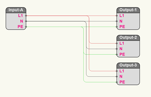
When editing a distributor's internal wiring, the device is displayed schematically, as a "device component" rectangle with the device inputs on the left, device outputs on the right, and two columns of circuit breakers in the middle (input and output breakers). Since the device is viewed from the inside, input sockets become outputs, and vice-versa.
Each socket displays as an object consisting of multiple pins; the number of individual pins depends on the type of connector. Each pin is a connection point—either a source or a destination. Destination pins have control points that can be dragged onto the source pins of other sockets to create internal connections; a polyline shows the connection, in specific colored classes that correspond to local codes.
In addition to sockets, internal elements such as circuit breakers (or fuses) provide a useful common connection point for multiple power destinations that are fed from a single source. These are, like the sockets, represented by device component objects. Busbars, which are common connection points primarily used for gathering neutral and earth conductors, are also represented by device components.
When a symbol contains an electrical component object, Power Information parameters display on the symbol's Object Info palette to enable power patching; see Power patching from the Object Info palette for more information.
To edit a distributor's internal connectivity, customize an existing distributor, or create a custom distributor:
Do one of the following:
Locate the symbol definition of an existing distributor in the Resource Manager. Proceed to Step 2.
If the distributor you need does not already exist in the file, use the Distributor tool to place a distributor similar to the one you wish to edit or customize. Proceed to Step 2.
Create a symbol out of a custom 3D object that you have designed; attach the Distro record and the ConnectCAD Device Definition record to the symbol definition (see Attaching record formats to a symbol definition); the Category to select in the record is Power. Edit the symbol definition's device properties by right-clicking and selecting Edit Device Definition from the context menu. See Editing the device definition data for information on how to define the device's parameters and sockets. From the Edit Device Definition dialog box, click Save and Enter Internal Wiring, and proceed to Step 3. Alternatively, in the Resource Manager, locate the symbol definition of the custom distributor, and proceed to Step 2.
Copy the internal wiring from one distributor symbol definition to another one or to several others. In the Resource Manager, select the distributor symbol definition (or definitions) to be customized. Right-click and select Copy Internal Wiring from from the context menu. The Select Symbol dialog box opens; select the symbol definition that serves as the source of the internal wiring settings. Click OK to copy its internal wiring properties to the previous Resource Manager symbol definition selection.
Right-click on the symbol definition and select Edit Internal Wiring. In object editing mode, available tools display in a special Device Component Edit palette. This palette is only available within the editing mode.
If the command is not available, the symbol doesn't include the proper records and has no internal editing functionality.
Click the Device Component tool to add a socket, fuse, or busbar to the wiring. Click the mode that matches the orientation for the socket or the type of component; this can be changed later from the Object Info palette.
Click to insert the device component. Distributor outputs are placed on the right, and distributor inputs are placed on the left. Fuses and busbars are typically in the center, between the sockets.
The device component parameters can be edited from the Object Info palette.
Click to show/hide parameters.Click to show/hide parameters.
|
Parameter |
Description |
|
Name |
Specifies the name of the device component. The Spotlight Numbering command can be used to name/number several components at once. |
|
Type |
Selects the type of device component, similarly to the mode selection at insertion |
|
Signal |
Selects the type of signal carried by the device component. The list of available signals displays according to priority (uncategorized, custom, workgroup, and default). Select --- to indicate a passive signal, $$$ for a proprietary signal, or select ADAT for an unknown type of signal. |
|
Connector |
Select the type of connection leading to the device; the list of available connectors for the selected signal displays according to priority (uncategorized, preferred, custom, workgroup, and default). Select --- to indicate that there is no connector, or select ??? for an unknown type of connection. |
|
Chassis Connector |
Displays the type of connector on the device |
|
Power consumption/ voltage/ power factor (Input only) |
Displays the specifications of the component (power consumption, voltage per phase of the power source, and power in amps per phase) |
|
L1, N, PE (Output only) |
Each destination pin (live, neutral, protective earth) can be connected to a single source pin; the connector pins display together with the source feeding each pin. Click on the list to view all of the source pins and select a different one if needed. |
|
Maximum Power/ Voltage (Output only) |
Displays the limiting specifications of the component |
|
Rating/ Ampere (Fuse only) |
Displays the type, sensitivity, and the breaker amperage of the overcurrent protector |
|
IN (Bus only) |
Lists the fuse outputs that can be connected to the bus; select a different one if needed |
|
Is loop-thru |
Indicates that the socket is a loop type |
Use the Selection tool to connect the output pin of a device component to an input socket (or to an inline fuse or bus) by clicking and dragging the control point, or by specifying the connection from the Object Info palette (enter text in the search box to filter the list). When multiple device components are selected, you can connect many destination pins to a common source pin, for example when connecting neutral and earth which all normally have the same pin names.
Connecting a live phase 1 pin from output to input
Standard regionally-specific colors are used for the connections so that they are easily recognizable. The colors are set by class, in case an adjustment is needed for local or international standards. By default, the colors age:
|
Pin |
Usage |
Color |
|
L1 |
Live Phase1 |
Black |
|
L2 |
Live Phase 2 |
Red |
|
L3 |
Live Phase 3 |
Blue |
|
N |
Neutral |
White |
|
PE |
Protective Earth |
Green |
Other edits include changing connections, removing device components, and otherwise reconfiguring the device to customize it as needed.
When the distributor has been edited, exit object editing mode to return to the drawing.
Any existing distributors in the file that are based on the edited symbol definition update to reflect the changes.
Copying internal wiring to several devices
You can copy the internal wiring connection settings from one device symbol definition to another, or to several others, through the Resource Manager.
To copy the internal wiring from one device definition to another:
Select the symbol definition (or multiple symbol definitions) from the Resource Manager.
Right click, and select Copy Internal Wiring from from the context menu.
The Select Symbol dialog box opens. Select the symbol to use as the source of the internal wiring connections.
Click OK to apply the wiring to the originally selected symbol definition.
