 Concept: Schematic viewsConcept: Schematic views
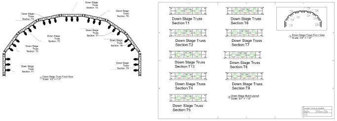
The Create Schematic View command generates dynamic schematic views of 3D rigging designs. Schematic views show a specified 2D view of rigging and load objects, no matter their orientation or the view settings in the model. From the same design layer geometry, you can create 2D shop drawings and custom 3D model views. For example, create a schematic Top/Plan view of an arched truss system and its attached lights, while using the same model for section viewports.
Schematic views are interactive; schematic rigging and load objects can be moved, rotated, mirrored, and so on. When a schematic rigging object is repositioned, the associated loads move with it and maintain their rotation angles relative to the schematic rigging object.
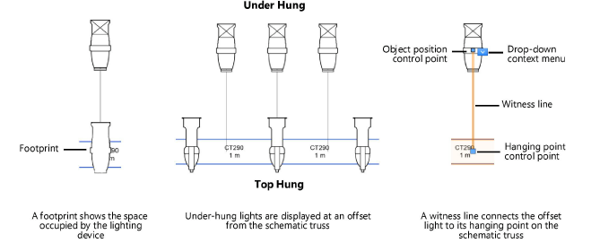
Schematic loads can also display at an offset, for greater visibility. For example, if lighting devices are attached to the top and bottom of a truss, you can display the under-hung devices above the truss system in the schematic view. Witness lines are drawn to indicate the devices’ hanging points on the truss. Hanging points define where the associated loads are calculated (Braceworks required). Optionally, a footprint can be shown on the schematic rigging object to indicate the space occupied by the load.
To control their attributes and visibility, set the class of witness lines and footprints from the Spotlight preferences: Loads and rigging pane.
The model and its schematic instances are linked. They interact in the following ways:
● In the model or in the schematic view, moving a load’s hanging point on the associated rigging object updates the load’s position in the corresponding view.
● If a load is repositioned in the model, and its schematic equivalent is offset, only the hanging point of the offset load moves on the schematic rigging object. The load’s offset position does not change, but its witness line updates to stay connected with the new hanging point. See Moving schematic loads by control points .
● Moving a schematic load to an offset position does not affect the model.
● Associating or disassociating loads from a model rigging object updates the schematic view by adding or deleting schematic loads.
● Deleting rigging and load objects from the model removes all schematic instances.
● If a model rigging object is deleted, its schematic instances are deleted along with all associated schematic loads.
● Deleting a schematic object does not affect the model parent.
● When Numbering light plot objects, the model objects and their schematic instances are considered to be identical. For automatic numbering, the location of the schematic objects determines the numbering order.
● A schematic lighting instrument shows the 2D label legend of its parent instrument.
|
Action in model |
Result in schematic view |
|
Move a load's hanging point on the associated rigging object |
Moves the corresponding load on its rigging object |
|
Rotate a load |
None |
|
Move or rotate a rigging object |
None |
|
Add a load to a rigging object |
Adds a load on the corresponding rigging object in the same relative position as the model |
|
Remove or delete a load |
Deletes the corresponding load |
|
Delete a rigging object |
Deletes the corresponding rigging object and any attached loads |
|
Number light plot objects |
Numbers the corresponding objects |
|
Update a lighting instrument’s 2D label legend |
Updates the 2D label legend of the corresponding instrument |
When the 3D model is edited, schematic views may not update automatically to reflect the changes; see Updating schematic views for more information.
|
Action in schematic view |
Result in model |
|
Move a load's hanging point on the associated rigging object |
Moves the corresponding load on its rigging object |
|
Move a load to an offset position |
None |
|
Rotate a load |
None |
|
Move or rotate a rigging object |
None |
|
Add a load to a rigging object |
None |
|
Remove or delete a load |
None |
|
Delete a rigging object |
None |
|
Number light plot objects |
Numbers the corresponding objects; for automatic numbering, the order is determined by the location of the schematic objects |
|
|
Click here for a video tip about this topic (internet access required). |
~~~~~~~~~~~~~~~~~~~~~~~~~
