 Structural gridsStructural grids
|
Tool |
Tool set |
|
Grid Line
|
● Dims/Notes ● Building Shell |
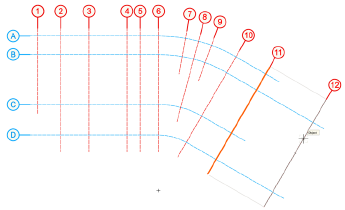
The Grid Line tool creates a snappable grid of reference lines that can be used for proper alignment of columns, walls, and other drawing elements. Structural grids consist of one or more grid sequences. Grid sequences, in turn, consist of multiple individual grid lines that use the same label system. Grid lines can be straight or based on an open polyline shape. They can be placed individually in any position needed, but placement options make it easy to insert them parallel or perpendicular to other lines, or in a radial format.
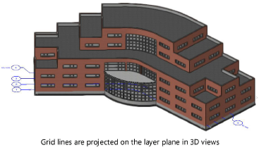
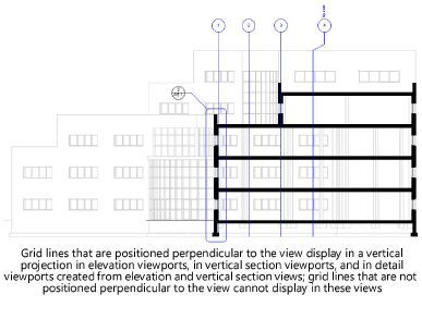
Grid lines are planar objects that are always placed on the layer plane of a design layer. They’re visible in Top/Plan view. In 3D views, they display projected on the layer plane on which they are drawn. You can also make grid lines visible within viewports. For elevation viewports, vertical section viewports, and detail viewports created from elevational views, only grid lines that are perpendicular (normal) to the view can be shown. The appearance of grid lines can be customized within each viewport as needed without affecting the grid line definition object in the design layer; see Structural grid visibility in viewports.
Grid lines can also be exported in an IFC-compliant format. See Exporting IFC data for structural grids for information on how grid lines and grid sequences are exported to IFC, and how to organize them in the file for proper export.
|
|
Click here for a video tip about this topic (internet access required). |
~~~~~~~~~~~~~~~~~~~~~~~~~

