 Inserting cablesInserting cables
Tool |
Tool set |
Cable
|
Preview |
The Cable tool places cables in the drawing by following a cable path object, following a rigging object like a truss or pipe, or inserting them independently.
Normally, the tool connects distributors to one or more electronic devices, creating a “cable object.” A cable object can also be called a cable run, since it consists of cable parts connected end-to-end to create a length of cable as drawn. The cable parts used in the cable run depend on the selections in the cable inventory (when managing cable parts) and the cable preferences. The cable style determines the type of cable (multi, feeder, jumper, or data) and its connections. A cable is considered a load, and can be included in load calculations (Braceworks required).
The truss path behavior depends on whether the cable connects to a distributor object on the truss. If you click on a truss and then click on a distributor object on the same truss system, the cables will automatically follow the truss system path, using the most efficient route to reach the distributor object. If, instead, you want to connect to an electronic device, like a lighting device or loudspeaker, click along the truss system to manually set the path.
The drawn cable assumes the height of connected objects, such as rigging objects and distributors; a vertical segment is automatically added if needed. When drawing in a 3D view, a cable can be created with a height without requiring existing geometry; the cable height is taken directly from the cable path object, the rigging object (the trim height of the top of the truss), or edges and vertices of other 3D geometry. When drawing in Top/Plan view, snapping from the ground plane to connecting, elevated geometry is required to create a cable jump.
Cables can be labeled with data tag objects; see Using data tags.
Mode |
Description |
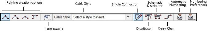
Polyline creation options |
Selects the method for drawing the polyline upon which the object is based; see Creating polylines |
Fillet Radius |
For Arc Vertex polyline mode, enter the fillet radius |
Cable Style |
Opens the Resource Selector to select a cable resource for placement; double-click a resource to activate it |
Single Connection |
Connects a distributor to an electronic device with a single cable |
Distributor |
Connects a distributor to one or more electronic devices following a drawn path, creating a cable for each output connection |
Schematic Distributor |
Connects a distributor to one or more electronic devices, displaying a direct, schematic route that illustrates the connections between the distributor outputs and the devices |
Daisy Chain |
Connects a distributor object to one or more electronic devices in a chain configuration, all using the same distributor output |
Automatic Numbering |
Enables automatic numbering of cables as they are placed |
Numbering Preferences |
Set the default parameters for automatic numbering of cables |
Regardless of the cable mode, when inserting a cable on a distributor object, choose the output for the cable connection. Only Single Connection mode does not require a distributor in the connection; the other modes do require a distributor.
To select the output for the cable:
1. When using the Cable tool to place a cable, click on a distributor object (or in Daisy Chain mode, on a fixture).
The Select Output dialog box opens.
![]() Click
to show/hide the parameters.
Click
to show/hide the parameters.
2.When no outputs are free, an error message displays. Select a different distributor with free outputs to create the cable run.
~~~~~~~~~~~~~~~~~~~~~~~~~
