 Placing
jackfields and linked jackfieldsPlacing
jackfields and linked jackfields
Placing
jackfields and linked jackfieldsPlacing
jackfields and linked jackfieldsTool |
Tool set |
Jackfield
Linked Jackfield
|
Schematics |
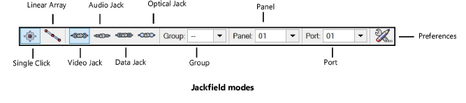
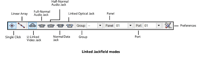
The tools place jackfields or linked jackfields, of the video, audio, optical, or data type.
Mode |
Description |
Single Click |
Places a single jack or linked jack at the click location |
Linear Array |
Places an array of jacks or linked jacks along the drawn line |
Video Jack/ U-Linked Video Jack |
Inserts a video jack or a U-linked video jack type of specialized device |
Audio Jack/Full-Normal Audio Jack/ Half-Normal Audio Jack |
Inserts an audio jack or full or half normal audio jack |
Data Jack/Normal Data Jack |
Inserts a data jack or normal data jack |
Optical Jack/Linked Optical Jack |
Inserts an optical jack or linked optical jack |
Group |
Assigns the panel to a named group of jackfields. This extends the name space of large patching systems by adding a group prefix in front of the row/column value. |
Panel/Port |
The panel and port number are set according to the options in the ConnectCAD settings |
Preferences |
Opens the Jackfield Preferences dialog box, for setting default values |
To insert a jackfield or linked jackfield:
1. Click the tool, and select the placement mode.
2.From the Tool bar, select the type of jack or linked jack to place by clicking the mode.
3.Click Preferences to open the Jackfield Preferences dialog box. Specify the default information for the devices to place.
![]() Click
to show/hide the parameters.
Click
to show/hide the parameters.
4.Specify the Group, Panel, and Port by selecting the values from the lists on the Tool bar. By default, the values from the ConnectCAD settings are applied (see Specifying ConnectCAD settings), but they can be overridden here.
If you continue placing the same jackfield device, these values automatically increment.
5.Click to place the jack or linked jack into the drawing. If placing the device into an existing circuit, the device splits the circuit.
● In Single Click mode, click once to place the object.
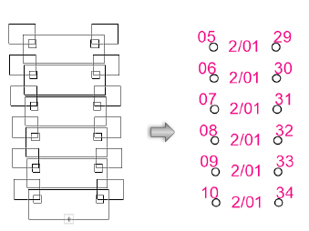
● In Linear Array mode, click once to start the array; move the cursor to set the distance and direction of the linear array. Press the Shift key to constrain to the horizontal or vertical direction. The preview indicates the spacing and placement of the objects; the floating Data bar shows the Count. Click to place them.
The device can be edited later from the Object Info palette.
![]() Click
to show/hide the parameters.
Click
to show/hide the parameters.
~~~~~~~~~~~~~~~~~~~~~~~~~

