Stair
settings: Graphic Attributes tabStair
settings: Graphic Attributes tab
Stair
settings: Graphic Attributes tabStair
settings: Graphic Attributes tabThe settings on the tab can be saved as a set and then loaded, replacing the current tab parameters.
1. Click the Graphic Attributes tab to specify the appearance of stair parts.
![]()
![]() Click
to show/hide the parameters.
Click
to show/hide the parameters.
Parameter |
Description |
Attributes Settings |
Saves settings so they can quickly be applied again; see Using saved sets for stair settings |
View |
Determines the view to apply the parameters to the stair; depending on drawing settings like layer scale and the document preference Hide details, the detailed or schematic view status is displayed |
Detailed |
Applies the graphic attributes to stairs in a detailed layer scale view |
Schematic |
Applies the graphic attributes to stairs in a schematic scaled view |
Accept for all views |
Applies the graphic attributes to stairs in all views (detailed and schematic) |
Graphic Attribute Settings |
Lists all geometry and text parameters that have graphic attributes settings, divided by 2D and 3D attributes. Click the disclosure arrow to reveal further parameters under certain categories. Each category’s current class, fill, pen, line style, line thickness, opacity, and if applicable, material and/or texture is displayed. Double-click a line to set attributes. If a material resource is used to define a part, the material typically provides the fill, texture, physical attributes, and construction information needed for drawings, renderings, and reports. To specify a material, select Use Material and select a material from the Resource Selector. The Fill and Texture settings are set to the material’s settings, and the Fill parameters are disabled. For Texture, select whether to use the class texture, to use the material’s texture, to select a different texture, or to use no texture. To control appearance and visibility, select a class from the list of classes present in the drawing, or create a new class. Select <Stair Class> to place the attributes in the same class as the stair object. |
2D Walk Line and Markers |
In addition to the class, pen, fill, and other “typical” attributes, the walk line and markers have specific parameters. The Double Line, Oval, and Filled Arrowhead marker styles are available especially for stair walk lines to meet DIN requirements. |
Start Marker |
Sets the graphics for the beginning of the walk line arrow that indicates the Up direction of travel on the stair, from the bottom tread, or start, of the stair |
End Marker |
Sets the graphics for the end of the walk line arrow that indicates the Up direction of travel on the stair, at the top, or end, of the stair |
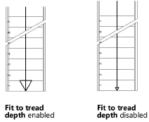
Fit to tread depth |
Fits the line end marker of the walk line to the depth of the tread
|
Stair Structure |
In addition to the “typical” attributes, the stair structures have an extra parameter. Stair structures can be designated as structural, allowing their appearance to merge with other structural objects in the cut plane of section viewports. Merged objects display as a single unit with one continuous fill. See Advanced section viewport properties for more information. To designate a stair structure as structural, double-click the stair structure item (top face, bottom face, front face, inside/outside), and select Merge Structural Objects in Sections from the Attributes dialog box. |
Set Class Style |
Sets each attribute (fill, pen, line style, line thickness, opacity, and texture) of all stair parts to the “By Class” setting, except for fill settings that are defined by a material. The attributes are then controlled by the class assigned to the part. (See Setting class attributes.) To set only the opacity by class, select the Use Class Opacity option when defining the graphic attributes for each category. |
Remove Class Style |
Removes the “By Class” setting for each attribute of all stair parts. The attributes are then controlled by the individual attribute settings, including material associations, made for each part. |
Apply to All Stairs |
Applies all the attribute settings of the current stair to all stairs in the file, including symbol definitions and stairs that may be within groups. Use caution when selecting this option, as it affects all stairs in the file. |
2.The graphic attributes of each stair part are listed. Double-click an item to edit it.
An Attributes dialog box with the name of the item is displayed. See The Attributes palette for information on setting attributes.
~~~~~~~~~~~~~~~~~~~~~~~~~
Stair settings: 2D Graphics tab
Stair settings: Construction tab
Setting minimum and maximum values for stair geometry