 Concept: Truss magnets
The truss symbols in the Vectorworks libraries use magnets to define the truss connection options. Magnets are located in the truss symbol's 3D component at each connection point. They are placed in the Rigging-Truss-Magnet class, which is invisible by default.
You can change the magnet class from the Results Display pane in the Braceworks preferences. This change does not affect existing magnets.
If you use trusses from the vast array of content libraries available with Spotlight and Braceworks, magnets are already inserted for you. Still, it's useful to learn about magnets for informational purposes—to understand the proper way to insert trusses and be able to fix the occasional truss connection issue. Advanced users who create custom truss content can add magnet functionality, either when creating new truss symbol definitions or when updating and fixing legacy content. There are multiple ways to add magnets:
Insert magnets based on the Connection data in the Truss Properties dialog box. If the data is correct, magnets will be automatically inserted in the correct position. This method is recommended for standard straight truss, L-corner, and circular truss symbol definitions. See Inserting magnets based on truss data.
Use the Magnet tool to precisely place magnets in the truss symbol definition's 3D component. This method is recommended for trusses with complex geometry, such as roof trusses, hub trusses, custom corners, and mid-span connection trusses. See Placing magnets manually. For tips about magnet placement in complex truss objects, see Adjusting magnets.
Trusses with magnets are compatible with old trusses when exported to a previous version file (prior to Vectorworks 2022). Exceptions are hub, roof, and mid-span connection trusses.
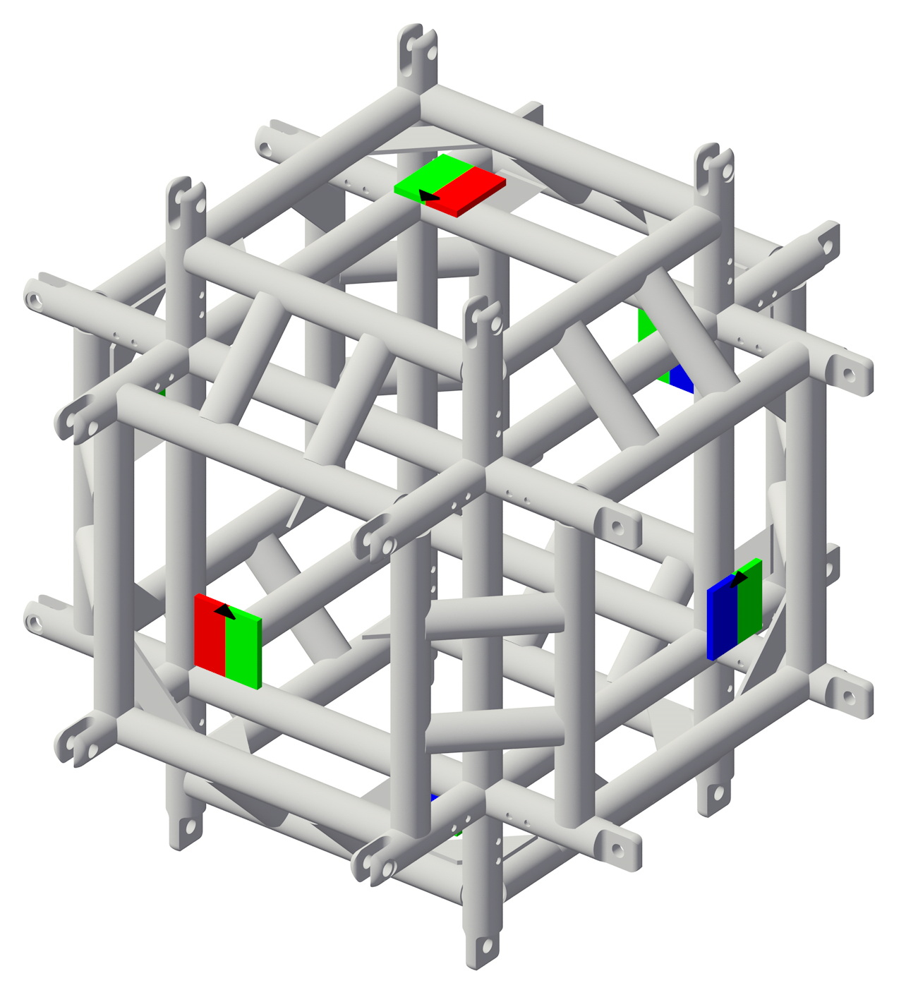
6-way spigot truss corner with male and female magnets
Magnets are color-coded by gender. Neutral magnets can only connect to other neutral magnets. These are used for conical and bolt connections. Male magnets can only connect to female magnets, and vice versa. These are used for spigoted and forked connections.
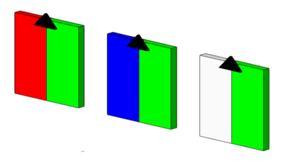
Female, male, and neutral magnets
A black arrow marks the magnet's orientation, which controls the default orientation of the connecting truss. Additional roll angles can be applied to the connecting truss if the option to Allow Extra Roll Angle is specified in the Magnet properties. The arrow side of the magnet must be facing outwards to connect with other magnets.
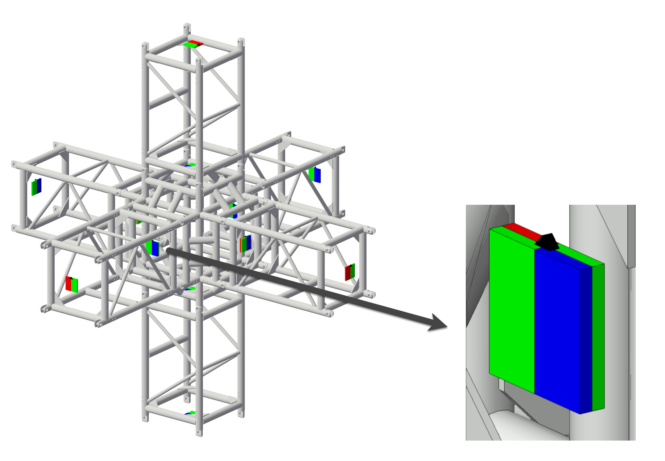
Magnets in connected spigot trusses
When adding trusses to an existing system, the cursor position is important. It determines which magnet controls the connection and it orients the connecting truss.
The magnet that is closest to the cursor on the existing truss is used for the connection.
When adding trusses in Top/Plan view, the connecting truss is inserted by its start magnet when the cursor hovers over the right side of the existing truss profile. However, the connecting truss is inserted by its end magnet (thereby flipping the truss) when the cursor hovers over the left side of the existing truss profile. This means that if the connecting truss changes direction, as in L-corner and curved pieces, it points to the left when the cursor is on the right side of the truss profile, and it points to the right when the cursor is on the left side of the truss profile.
When adding trusses in a 3D view, the connecting truss can be rolled if extra roll angles are enabled for the existing truss's magnet. When the cursor hovers over the right, bottom, or left side of the existing truss profile, the connecting truss can be inserted at a roll angle of 90°, 180°, or 270°, depending on the Allow Extra Roll Angle setting.
