Adjusting magnets
The magnets inside of a truss symbol control the truss connection options. If your custom trusses aren't connecting properly, try changing the properties or placement of magnets to fix the connection. Adjustments may be needed if the truss symbol has unusual custom geometry or if magnets were inserted based on invalid truss Connection data.
When a truss magnet is properly configured:
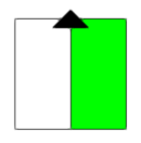
Its center point aligns with the center of the truss profile (also the center of the truss cross).
In mid-span connection trusses, which have multiple connection sites along the truss profile, the center point of the magnet must align with the center of the connection site; see Mid-span connection truss.
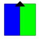
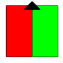
Its orientation matches the hanging angle of the truss connection.
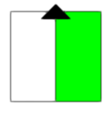
Its connection side (with the arrow) faces outwards, towards the connecting truss.
Its arrow points to the orthogonal top of the truss profile.
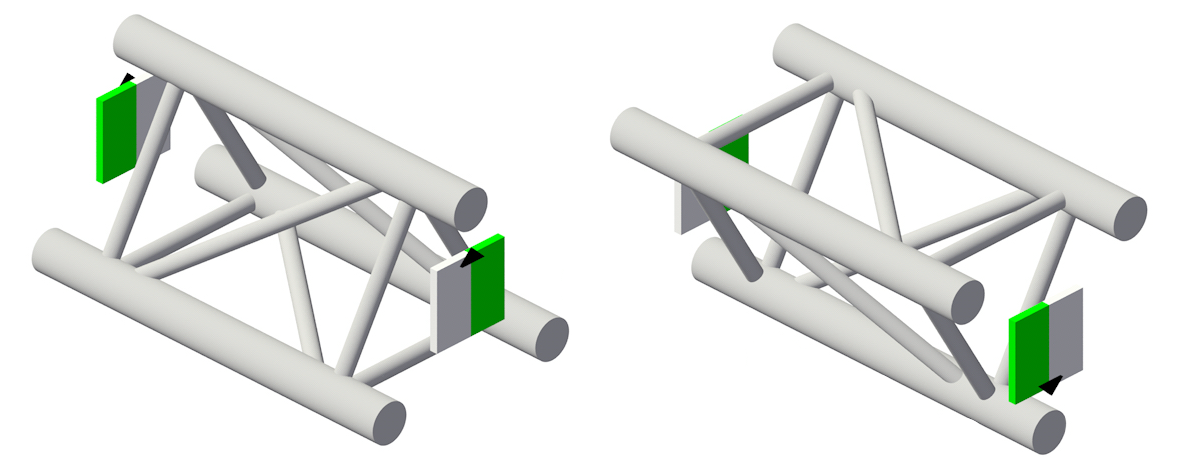
Properly configured magnets in triangle trusses
To check and adjust the truss magnets:
Open the truss symbol's 3D component in Object editing mode. There are several ways to do this:
Click Edit Magnets in Symbol from the Truss Properties dialog box; see Setting custom truss parameters for a description of the dialog box.
Select a truss symbol instance in the drawing, and select Edit 3D Component from the context menu.
Select the truss symbol in the Resource Manager, and select Edit 3D Component from the context menu.
In the edit window, select a magnet. The properties display on the Object Info palette.
To adjust the magnet:
Edit the Magnet properties.
Manually reposition the magnet. It may be helpful to draw layout lines connecting the mid-points of opposite sides of the truss profile. The lines intersect at the center point, where the magnet must be placed. Use the Move by Points tool to move the magnet to the center point. If needed, use the Rotate tool to spin the magnet to the correct hanging angle.
Magnet properties
View and edit the magnet properties from the Object Info palette, which also displays when Placing magnets manually.
Click to show/hide the parameters.Click to show/hide the parameters.
|
Parameter |
Description |
|
X/Y/Z |
Sets the magnet location |
|
Roll Angle |
Rotates the magnet on its X axis; this value sets the default roll angle of the connected truss |
|
Hanging Angle |
Rotates the magnet on its Y axis; this value sets the hanging angle of the connected truss |
|
Rotation |
Rotates the magnet on its Z axis; this value sets the rotation of the connected truss |
|
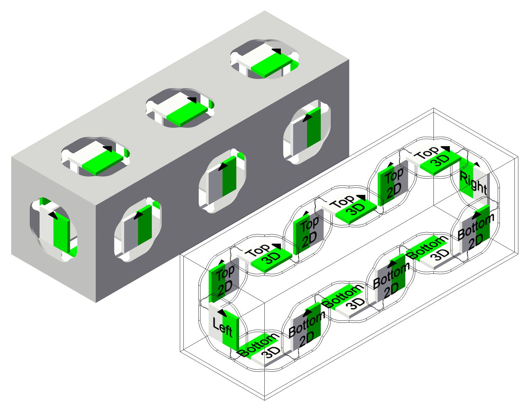
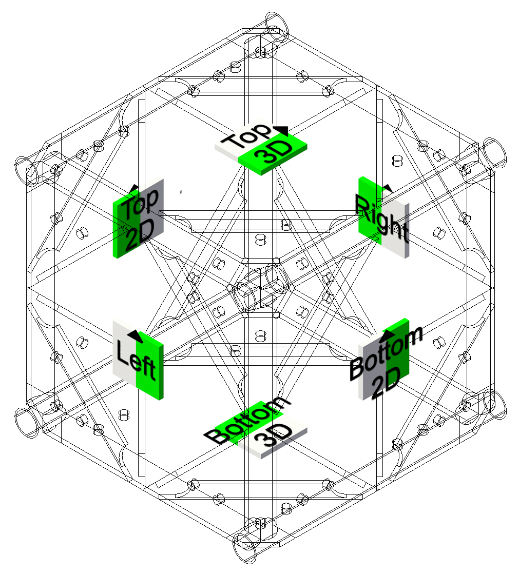
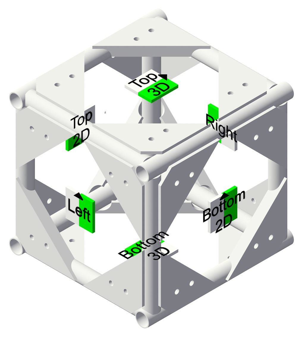
Connection Type |
Sets the type of truss connection
The options correspond to the six connection types in a custom truss corner, shown here in a left isometric view |
|
Gender |
Sets the truss gender: Neutral
Male
Female
|
|
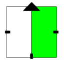
Allow Extra Roll Angle |
Allows additional roll angles for the connected truss. The options are indicated by black rectangles on the magnet. Triangle trusses do not support roll angles. None: The connected truss will always align with the magnet arrow.
180°: The connected truss can align with the magnet arrow or connect at a 180° angle, depending on the cursor position.
90°, 180°, 270°: The connected truss can align with the magnet arrow or connect at a 90°, 180°, or 270° angle, depending on the cursor position.
|
Complex configurations
In truss symbols with unusual custom geometry, the magnets may need adjustments.
The examples below indicate the type of magnets needed and where they must be placed in complex corners, hubs, and mid-span connection trusses such as grid and mod trusses.
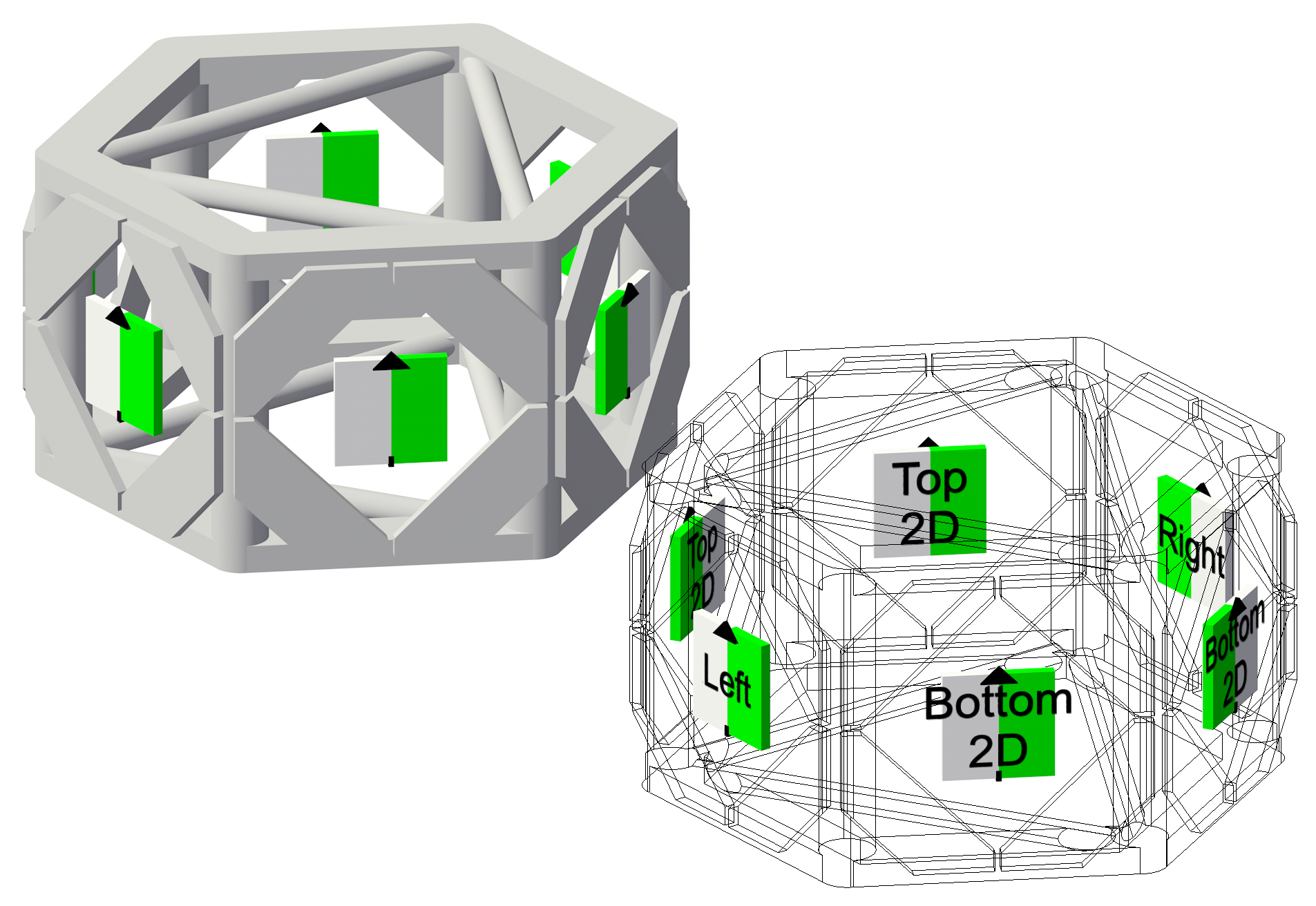
6-way corner truss
Hub truss
Mid-span connection truss