 Inserting doors
|
Mode |
Tool |
Tool set |
Shortcut |
|
Modes for The Symbol Insertion tool |
Door
|
Building Shell |
Alt+Shift+D (Windows) Option+Shift+D (Mac) |
To insert a door:
Click the tool and appropriate mode.
Alternatively, if placing a curtain wall door into a curtain wall, select a panel with the Edit Curtain Wall tool, and then right-click on the panel and select Insert Door from the context menu. The door is automatically inserted as a curtain wall door.
Do one of the following:
Click Door Style on the Tool bar to select a resource from the Resource Selector.
Individual manufacturer catalog items cannot be selected using the Resource Manager; see Concept: Plug-in object styles and catalog items.
Click Preferences to open the Door Preferences dialog box and specify the tool’s default parameters.
The parameters can be edited later from the Object Info palette. Additional parameters are available from the Object Info palette itself, as described in Door properties.
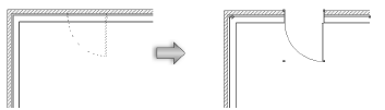
Click in the drawing area or in a wall to set the insertion point of the door, and click again to set the rotation. The direction of a door inserted in a wall can be changed later by clicking Flip from the Object Info palette or from the context menu.
Several features of the door are described as “interior” or “exterior.” These include trim and wall-wrap parts. These elements are determined based on the internal and external faces of the wall. The left side of the wall (as viewed along the wall direction) is always “exterior,” and the right side is “interior” (see Wall direction). Flipping the door does not flip these elements.
Optionally, create a style resource from an unstyled object (see Custom plug-in object styles with catalog options).
Door settings
You can create plug-in objects with a combination of parameters that are determined by the manufacturer’s catalog item, by style and/or by instance, and then optionally save them as a plug-in object style. Catalog parameters have a fixed value established by the manufacturer and cannot be edited by the user. Style parameters have a fixed value established by the style; instance parameters can be set independently for each instance of the object in the drawing (see Concept: Plug-in object styles).
Additional plug-in object settings for the class, the 2D component and cut plane display, and wall insertion are available; see Additional plug-in object style and instance options.
Click to show/hide the parameters.Click to show/hide the parameters.
|
Parameter |
Description |
|
Use Style |
To create a custom door, leave the Unstyled setting. To use an existing door from the resource libraries, click Use Style; from the Resource Selector, double-click a resource to activate it. |
|
Convert to Unstyled |
If Use Style is currently set to a style, select this option to convert the object to unstyled; the current values are retained, but all parameters on all panes are set to By Instance to allow editing |
|
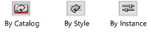
By Catalog/Style/Instance |
A graphic indicates whether each parameter within the style is set to By Catalog and defined by the catalog item, set to By Style and given a fixed value by the user, or set to By Instance and editable in the dialog box. An object style may have a combination of all three of these settings, to balance the need for consistency and flexibility. By Catalog/Style/Instance settings are established by the style and cannot be changed from the settings dialog box.
To edit the object style, see Editing plug-in object styles; editing the style modifies all plug-in objects in the file that use the style. |
|
Select from Catalog
|
If the catalog item is set by instance, opens the Catalog dialog box for Selecting catalog items for plug-in object styles. If a current catalog item is associated with the style, static text displays the item’s description. The catalog item itself can be set to By Style (to ensure that all objects using that style use the same catalog item) or to By Instance (if, for example, different sizes of the otherwise identical object require different catalog items). |
|
3D Preview |
Dynamically displays a 3D preview of the door with the currently selected parameters |
|
View |
Select the standard view for the 3D preview of the door |
|
Render |
Select the render mode for the 3D preview of the door |
|
Detail |
Select the detail level for the 3D preview of the door |
|
Top/Plan Preview |
Dynamically displays a Top/Plan preview of the door with the currently selected parameters |
|
Detail |
Select the detail level for the Top/Plan preview of the door |

Door settings: General pane
Click to show/hide the parameters.Click to show/hide the parameters.
|
Parameter |
Description |
|
Size Reference |
Select the appropriate option to define the door width and height; the Size Reference selection automatically updates the Width and Height fields, but does not change the size of the door: Leaf Size: this represents the door width and height that measures to the inside of the jamb, excluding the jamb, transom, and sidelights; this is the default setting for imperial units. Unit Size: this represents the current overall door width and height that measures to the outside of the jamb, including the jamb, transom, and sidelights. Rough Opening: this represents the current overall door width and height that measures to the outside of the jamb, including the jamb, transom, sidelights, and shim gap (for the Opening Configuration, the Size Reference is automatically changed to Rough Opening); this is the default setting for metric units. |
|
Width/Height |
The width/height of the door is measured based on the Size Reference selection: Leaf size: width/height of the door leaf is measured at the inside of the jamb. Unit Size: width/height is measured at the outside of the jamb. Rough Opening: width/height measures the rough opening. |
|
Select Use symbol geometry and click Browse to select a door symbol. Click the Symbols selector. From the Resource Selector, double-click a different symbol to apply it. The symbol Name displays in the Door Settings dialog box and the preview is updated with the selected symbol. When a symbol is selected, all fields pertaining to the door’s geometry are overridden by the symbol geometry; however, parametric values are still available for scheduling and reporting purposes only. |
|
|
Top Shape |
Select the shape of the top of the door |
|
Include transom |
Adds a transom above the door; transom parameters are set from the Transom pane |
|
Rise |
Enter the distance between the start of the top shape to the top of the door (not applicable for Square and Round Top Shape) |
|
Spring |
Enter the distance traveled above the floor before the Top Shape begins |
|
Insertion Relative to |
Specify whether the insertion point is relative to the exterior face, center, or interior of the jamb. Additional wall insertion options are available, as described in Additional plug-in object style and instance options. |
|
Curtain wall door |
Indicates that the door will be placed in a curtain wall, where its width and height are based on the surrounding frames where it is placed. A curtain wall door does not have as many available parameter options as a standard door. Configurations are limited to those that apply to curtain wall placement. |
|
Create niche for Space objects |
Creates niche geometry that space objects can include in their net boundary areas; see Space settings: 2D Boundaries and Area pane |
|
Configuration |
Select the general door configuration. To create a simple opening in a wall for defining a door break without creating any geometry to represent the door, select the Opening option. Depending on the selection, a variety of door settings are enabled or disabled automatically, as described in the following sections. |
|
Operation |
Select the advanced operation for the Configuration. For sliding and swing doors, “O” represents a fixed door and “X” represents an operating door. |
|
Leaf Number |
Enter the number of leaves for a Barn, Pocket, or Sliding Configuration (Multiple or Multiple Bi-part Operation). For a Barn Configuration, specify the number of leaves to slide to the left/right. For a Pocket or Sliding Configuration Multiple Operation, valid values range from 2–20. The first leaf of a sliding door is fixed, and each additional leaf is offset and slides beside the previous leaf. The leaves open on the left. For doors in a wall, you can open the leaves on the right by clicking Flip on the Object Info palette. For a Pocket Configuration Multiple Bi-part Operation, valid values range from 3–20. For a Sliding Configuration Multiple Bi-part Operation, valid values range from 4–20. The first leaf on each side of a sliding door is fixed, and each additional leaf is offset and slides beside the previous leaf. For Pocket and Sliding Configuration Multiple Bi-part Operation doors, if the Leaf Number is an even number, an equal number of leaves opens on the left and the right. If the Leaf Number is an odd number, an additional leaf opens on the left. For doors in a wall, you can open the additional leaf on the right by clicking Flip on the Object Info palette. |
Door settings: 2D Visualization pane
Click to show/hide the parameters.Click to show/hide the parameters.
|
Parameter |
Description |
|
Draw wall lines |
Draws wall lines at all times; wall lines are drawn in the Ceiling-Main class to easily create reflected ceiling plans |
|
Show operation direction for sliding and pocket doors |
Displays the direction indicators for a Sliding or Pocket Configuration |
|
Set Attributes By |
Select whether to set the 2D graphic attributes and visibility of the listed door parts by Object, Line Style, or Class. Object: disables line style and weight controls for individual parts, and uses the line style and weight settings for the door object. Line Style: controls line style and weight for the individual parts; these settings override the door object’s settings. To change the Direction Marker for pocket and sliding doors, choose the desired style from the marker list, or select Custom to create a custom marker. Select Edit Marker List to open the Edit Marker List dialog box; see Editing the marker list. Class: sets the line style and weight of individual parts (and markers for Direction Markers) by class. To control appearance and visibility, select a class from the list of classes present in the drawing, or create a new class. Select <Door Class> to place the part attributes in the same class as the door object. |
|
Visibility Classes |
To control appearance and visibility, select a class for each part from the list of classes present in the drawing, or create a new class. Select <Door Class> to place the part attributes in the same class as the door object. |
Door settings: 3D Visualization pane
3D Visualization options are not enabled for the Opening Configuration.
Click to show/hide the parameters.Click to show/hide the parameters.
|
Parameter |
Description |
|
3D Hinge Direction Marker |
Draws lines representing the 3D hinge direction |
|
Show interior/exterior marker |
Draws lines representing the hinge direction of the door leaves on the interior/exterior side of the door in 3D |
|
Use hinge marker class attributes |
Sets the hinge direction marker’s attributes by class |
|
Hinge Direction Marker Class |
To control visibility and, if Use hinge marker class attributes is selected, appearance, select a class from the list of classes present in the drawing, or create a new class. Select <Door Class> to place the hinge marker attributes in the same class as the door object. |
|
Marker Points Towards |
Set the hinge direction marker to point toward the hinge or toward the handle |
|
Draw 3D open |
Draws 3D doors as open at the specified Open Angle. Enter the angle; valid values are: Barn, overhead, pocket, and sliding doors: 0°–100° Double acting and double egress doors: 0°–180° Folding doors: 0°–90° Swing doors: -180°–180° |
|
3D Detail Levels |
Vectorworks automatically produces door representations in low, medium, and high detail levels for display at different scales, but some door parts are left for you to determine. Set the detail levels for the listed door parts to display in a design layer view or viewport. The Muntins list item controls the display for all muntins in the door (in leaf, sidelights, and transom); Trim controls interior and exterior door trim; Hardware controls the detail level for all hardware selected in the Hardware pane of this dialog box. Vectorworks can automatically display the desired detail level based on the design layer’s scale; see Document preferences: Display tab. Different levels of detail can also display for different scale viewports. Once the door parts’ detail levels are established, set each viewport to display the desired Detail Level when creating the viewport, or set this from the Object Info palette. |
Door settings: ID Tag pane
Click to show/hide the parameters.Click to show/hide the parameters.
|
Parameter |
Description |
|
Include on schedule |
Includes this door’s information in the door schedule; see Creating door schedules |
|
Show tag in 2D |
Displays the ID tag in Top/Plan view |
|
ID Prefix |
Places a prefix before the label value |
|
ID Label |
Enter a label to identify the door |
|
ID Suffix |
Places a suffix after the label value |
|
ID Class |
To control visibility and, if Use ID class attributes is selected, appearance, select a class from the list of classes present in the drawing, or create a new class. Select <Door Class> to place the ID class attributes in the same class as the door object. |
|
Use ID class attributes |
Uses the ID class attributes for the bubble line, leader line, and leader line marker |
|
Keep ID horizontal |
When selected, automatically rotates the ID so that it is horizontal |
|
Bubble Shape |
Select the ID tag bubble shape |
|
Bubble Size |
Enter the minimum bubble size (this value represents the bubble size times the layer scale; the bubble shape is maintained relative to the text inside it for ID bubble uniformity throughout the drawing file) |
|
Bubble Line Attributes |
Select the bubble line attributes and weight, or select Set Thickness to open the Set Thickness dialog box for creating a custom line thickness |
|
Show leader |
Draws a leader line from the ID tag to the door object |
|
Line Attributes |
Select the leader line attributes and weight, or select Set Thickness to open the Set Thickness dialog box for creating a custom line thickness |
|
Include marker |
Includes a marker for the ID leader line; choose the desired style from the marker list, or select Custom to create a custom marker. Select Edit Marker List to open the Edit Marker List dialog box; see Editing the marker list. |
|
Show tag in 3D |
Displays the ID tag in 3D views |
|
Horizontal Offset |
Enter the horizontal offset of the 3D ID tag relative to the bottom left corner of the rough opening when looking at the exterior side of the door (a positive value moves the tag inside the opening relative to the starting corner; a negative value moves the tag outside the opening relative to the starting corner). The ID tag is offset slightly from the outside face of the door leaf. The size and shape of the text and bubble, if present, will match the plan settings, and the text will always be right reading from the outside of the wall. The bubble will scale with text scaling in viewports. |
|
Vertical Offset |
Enter the vertical offset of the 3D ID tag relative to the bottom left corner of the rough opening when looking at the exterior side of the door (a positive value moves the tag inside the opening relative to the starting corner; a negative value moves the tag outside the opening relative to the starting corner) |
Door settings: Configuration: Barn Door pane
Barn Door options are enabled only for the Barn Configuration.
Click to show/hide the parameters.Click to show/hide the parameters.
|
Parameter |
Description |
|
Leaf Size |
Displays the width and height of each leaf, calculated from size parameters on the General pane and the Leaf Overlap |
|
Leaf Overlap |
Enter the amount the leaves will extend past the outside edge of the trim and each other, on the Sides (when the door is closed) and the Top of the door. If there is no trim on the same side of the wall as the door panel, the leaves will extend past the outside edge of the jamb by the specified dimension. |
|
Leaf to Wall Clearance |
Enter the distance between the wall surface and the face of the leaf |
|
Leaf to Leaf Clearance |
Enter the distance between bypassing leaves |
|
Show Rail |
Select whether to display the rail hardware, and in which 2D/3D views |
|
Rail Type |
Select the rail type |
|
Rail Depth/Height |
Enter the depth and height of the rail |
|
Left/Right Side Extension |
Enter the distance on the left/right the rail should extend beyond the width required to clear the door |
|
Add door post of width |
For a Box Rail Type, adds a door post; enter the post’s width |
|
Show Rail Mounts |
For Flat and Round Rail Type, select whether to display the rail mounts in 3D views |
|
Distance from Rail Ends |
Enter the distance the first and last mounts are inset from the rail ends |
|
Maximum Spacing |
Enter the maximum spacing between rail mounts |
|
Bypass Bracket Type |
For Barn Configuration Bypass Operation, select whether to display the brackets, and the bracket type |
|
Show Leaf Hangers |
Select whether to display the leaf hangers in 3D views |
|
Leaf Hanger Mounting |
Select whether the hangers attach to the top or the front face of the leaf |
|
Leaf Hanger Offset |
Enter the distance between the edge of the leaf and the center of the door hanger |
|
Hanger Length/Width |
Enter the length and width of the door hanger |
|
Roller Diameter |
For Flat and Round Rail Type, enter the roller diameter |
Door settings: Configuration: Pocket pane
Pocket door options are enabled only for the Pocket Configuration.
Click to show/hide the parameters.Click to show/hide the parameters.
|
Parameter |
Description |
|
Leaf Size |
Displays the width and height of each leaf |
|
Leaf Side Overlap |
Sets the distance the door leaves overlap each other when closed |
|
Use Stile Width |
Sets the leaf side overlap to match the stile width of the leaf. When this field is selected, Leaf Side Overlap is automatically completed and disabled. |
|
Leaf to Wall Clearance |
Specifies the distance between the door leaves and the wall pocket |
|
Leaf to Leaf Clearance |
Specifies the distance between the door leaves |
|
Use exposed pocket recess |
Exposes the pocket cavity on one side of the wall |
|
Recess Depth |
Displays the distance between the door leaves |
|
Auto-calculate |
Automatically sets the recess depth as needed to contain the door leaves |
|
Include recess finish |
When Use exposed pocket recess is selected, adds a finish to the vertical surfaces of the pocket recess |
|
Recess Finish Thickness |
Sets the thickness of the pocket recess finish |
|
Recess Finish Attributes |
Specifies the class for the exposed pocket door recess finish: Outer Wall Component: The recess finish acquires the attributes and texture of its adjacent wall component. Pocket Door Recess Class: The recess finish acquires the attributes and texture set for the Pocket Door Recess class parameter on the Classes pane (see Door settings: Classes pane). |
Door settings: Configuration: Sliding pane
Sliding door options are enabled only for the Sliding Configuration.
Click to show/hide the parameters.Click to show/hide the parameters.
|
Parameter |
Description |
|
Leaf Size |
Displays the width and height of each leaf |
|
Leaf Side Overlap |
Sets the distance the door leaves overlap each other when closed |
|
Use Stile Width |
Sets the leaf side overlap to match the stile width of the leaf. When this field is selected, Leaf Side Overlap is automatically completed and disabled. |
|
Leaf to Leaf Clearance |
Specifies the distance between the door leaves |
Door settings: Jamb pane
Jamb options are not enabled for the Opening Configuration or for curtain wall doors.
In Double Acting and Double Egress configurations, the leaves are mounted so that they are centered on the jamb when they are closed.
Click to show/hide the parameters.Click to show/hide the parameters.
|
Parameter |
Description |
|
Width |
Enter the face width of the door jamb (parallel to the wall) |
|
Depth |
Enter the depth of the door jamb (perpendicular to the wall) |
|
Use wall depth |
Sets the jamb depth to the overall wall depth |
|
Auto-expand Depth for sliding and pocket configurations |
Automatically increases the jamb Depth as needed to receive sliding or pocket door leaves. The required jamb depth is equal to the total depth of the leaves and their clearances. Selecting this setting never decreases the jamb depth specified by other settings. |
|
Use jamb extension |
Select this field to specify a jamb extension to fill any gap between the interior face of the jamb and the interior face of the wall; enter the desired Jamb Extension Width. In 2D views, extensions use the Jamb line styles and weights; in 3D views, the extension fill color and/or textures and visibility are controlled by the Int. Jamb class. |
|
Shim Gap |
Enter the distance between the jamb exterior face and the rough opening (for the Opening Configuration, the Shim Gap is automatically set to 0) |
|
Show shim gap in plan |
Displays the shim gap in Top/Plan view |
|
Masonry Module |
Enter the masonry module dimension |
|
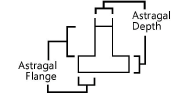
Astragal Flange/Depth |
Use these two dimensions to determine the size of the astragal flange or depth (enter zero to display without an astragal flange); enabled if Swing Configuration and Double Bi-part Operation are selected on the General pane
|
Door settings: Leaf pane
Leaf options are not enabled for the Opening Configuration.
Click to show/hide the parameters.Click to show/hide the parameters.
|
Parameter |
Description |
|
Leaf |
Select the desired leaf type |
|
Solid |
|
|
Thickness |
Enter the thickness of the door slab |
|
Include vision panels |
Includes vision panels |
|
Vision Panel Shape |
Select the shape of the vision panel |
|
Bottom Edge Offset |
Enter an offset value, measured from the bottom of the leaf to the bottom of the lowest vision panel |
|
Strike Edge Offset |
Enter an offset value, measured from the strike edge of the leaf to the nearest edge of the vision panel. With some of the more complex, multi-part door configurations, the offset is measured from different points to provide correct alignment of vision panels. Consult the 3D Preview to confirm the appearance. |
|
Panel Height/Width |
Enter the height/width of the individual vision panel. Panel Width is enabled only for the rectangle and oval vision panel shapes. For square and round, the width is automatically set equal to the height. |
|
Number of Panels |
Enter the number of vision panels |
|
Separation |
For leaves with more than one vision panel, enter the vertical offset between panels |
|
Set top panel height |
For leaves with more than one vision panel, makes the top vision panel a different height than the other panels; specify the desired Top Panel Height |
|
Glazing Thickness |
Enter the glazing thickness for the vision panels |
|
Glass |
The Glass leaf type enables the options specific to glass doors on this pane, such as Muntin Style; it does not make the door leaves render as transparent glass. To make the glass render properly, apply a Glazing class on the Classes pane. |
|
Thickness |
Enter the thickness of the door slab |
|
Top Rail Width |
Enter the width of the top door rail |
|
L/R Stile Width |
Enter the width of the left and right stile |
|
Bottom Rail Width |
Enter the width of the bottom door rail |
|
Muntin Style |
Select the muntin style |
|
Vertical/Horizontal Bars |
Enter the number of vertical/horizontal muntin bars |
|
Bar Width/Depth |
Enter the muntin bar width/depth |
|
Bar Offset |
Enter the muntin bar offset for Prairie muntins |
|
Glazing Thickness |
Enter the glazing thickness for the glass leaf |
|
Panel |
|
|
Thickness |
Enter the thickness of the door slab |
|
Top Rail Width |
Enter the width of the top door rail |
|
L/R Stile Width |
Enter the width of the left and right stile |
|
Bottom Rail Width |
Enter the width of the bottom door rail |
|
Vertical/Horizontal Panels |
Enter the number of vertical/horizontal panels in the door |
|
Mid Stile Width |
Enter the width of any interim stiles |
|
Set top panel height |
Makes the top door panel a different height than the other panels; specify the desired Panel Height |
|
Single top panel |
Draws only one panel across the top of the leaf, regardless of the number of panels below |
|
Glazing in top panels |
Inserts glazing in the top panel |
|
Glazing Thickness |
Enter the glazing thickness for glass in the top panel |
|
Muntin Style |
Select the muntin style |
|
Vertical/Horizontal Bars |
Enter the number of vertical/horizontal muntin bars |
|
Bar Width/Depth |
Enter the muntin bar width/depth |
|
Bar Offset |
Enter the muntin bar offset for Prairie muntins |
|
Custom |
|
|
Thickness |
Enter the thickness of the door slab |
|
Custom Leaf |
Select the leaf type from the default content; see Concept: Resource libraries. Custom leaves must be 3D-only symbols made from generic solids, saved in the default content location. |
Door settings: Second Leaf pane
Second door leaf options are enabled only for doors with a two-leaf Configuration and leaves of unequal widths; the narrower pane is considered the second leaf.
Click to show/hide the parameters.Click to show/hide the parameters.
|
Parameter |
Description |
|
Second Leaf |
By default, bi-part doors make both leaves the same Leaf setting (Glass, Panel, or Custom), Width, and Open Angle, but these settings can be changed |
|
Unequal leaf |
For double egress doors and doors having a double bi-part Operation, inserts a door with leaves of unequal widths |
|
Width Leaf 1/2 |
When Unequal leaf is selected, enter the width of the first door leaf; the width of the second door leaf is calculated automatically and displayed in the Width Leaf 2 value |
|
Custom open angle |
Displays the second leaf with a custom open angle for Top/Plan and 3D views. Enter the angle; valid values are: Barn, overhead, pocket, and sliding doors: 0°–100° Double acting and double egress doors: 0°–180° Folding doors: 0°–90° Swing doors: -180°–180° |
|
Include hardware |
Includes the hardware specified for the first leaf on the second leaf |
|
Set second leaf as solid |
Makes the second leaf solid; when deselected, the second leaf has the same Leaf setting as the first leaf |
|
Vision Panels |
|
|
Add vision panels |
Adds vision panels to the second leaf; select whether to make the panels the same width as vision panels on the first leaf, or enter a custom width. This option is available only when both leaves are solid and Include vision panels is selected for the first leaf. |
|
Muntins |
Adds muntins to the second leaf; select whether to use the same number of vertical bars as the first leaf, or enter a custom number. This option is available when both leaves are glass or are paneled with Glazing in top panels selected for the first leaf. |
|
Panels |
Adds panels to the second leaf; select whether to use the same number of horizontal panels as the first leaf, or enter a custom number. This option is available only when both leaves are paneled. |
|
Custom Leaf |
Select whether to use the same custom leaf symbol as for the first leaf, or select a different symbol from the default content. This option is available only when both leaves are custom. |
Door settings: Lights pane
Lights options are not enabled for the Opening Configuration or for curtain wall doors.
Click to show/hide the parameters.Click to show/hide the parameters.
|
Parameter |
Description |
|
Sidelights |
|
|
Include sidelights |
Adds sidelights |
|
Left/Right Width |
Enter the left/right sidelight width |
|
Sash Width/Depth |
Enter the sidelight sash width/depth |
|
Mullion Width/Depth |
Enter the sidelight mullion width/depth |
|
Use jamb depth |
Overrides the sidelight Mullion Depth with the jamb depth. When this field is selected, Mullion Depth is grayed. |
|
Glazing Thickness |
Enter the glazing thickness for the sidelights |
|
Muntins |
|
|
Include muntins |
Adds muntins to the sidelights |
|
Pattern |
Select the sidelight muntin pattern |
|
Vertical/Horizontal Bars |
Enter the number of vertical/horizontal muntin bars for Colonial muntins |
|
Bar Width/Depth |
Enter the sidelight muntin bar width/depth |
|
Bar Offset |
Enter the muntin bar offset for Prairie muntins |
Door settings: Threshold pane
Threshold options are not enabled for the Opening Configuration.
Click to show/hide the parameters.Click to show/hide the parameters.
|
Parameter |
Description |
|
Include threshold |
Includes a threshold |
|
(1) Interior Depth/(2) Exterior Depth |
Enter the interior and exterior threshold depth |
|
(3) Overall Depth |
Enter the overall threshold depth |
|
(4) Offset |
Enter how far to offset the threshold from the center of the door jamb |
|
(5) Thickness |
Enter the threshold thickness |
|
(6) Nosing |
Enter the threshold nosing height |
|
Threshold under leaf |
Limits the threshold to under the leaf; otherwise, to extend the threshold beyond the inside of the jamb, deselect this and enter the desired Extension width (this amount is applied to each side of the threshold, and negative values are not permitted) |
|
Z Offset |
Enter the Z elevation of the threshold |
Door settings: Louvers pane
Louvers can be applied to doors with all Configurations except Opening and Cased Opening.
Click to show/hide the parameters.Click to show/hide the parameters.
|
Parameter |
Description |
|
Replace with louvers for |
Select which parts of the door to replace with louvers; if Leaf panels is selected, all panels in the door are replaced |
|
Louver Type |
Select the louver type |
|
Preview |
The preview displays a profile view of the selected Louver Type and the parts to be dimensioned |
|
(1) Blade Spacing |
Enter the distance on center between the blades |
|
(2) Blade Angle |
Enter the blade angle, measured positively from horizontal |
|
(3) Blade Lip |
Enter the visible lip of the blade; for jalousies, enter the thickness of the blade |
|
(4) Louver Depth |
Enter the depth of the louver assembly |
|
Add louver frames in leaves |
Adds frames around the louvers; enter the Depth and Width |
Door settings: Transom pane
Transom options are not enabled for the Opening Configuration or for curtain wall doors.
Click to show/hide the parameters.Click to show/hide the parameters.
|
Parameter |
Description |
|
Sash |
|
|
Sash Width/Depth |
Enter the transom sash width/depth |
|
Sash Offset |
Offsets the sash from the center of the jamb. A positive value moves the sash toward the exterior of the door, and a negative value moves the sash toward the interior of the door. |
|
Mullion |
|
|
Mullion Width/Depth |
Enter the transom mullion width/depth |
|
Use jamb depth |
Overrides the transom Mullion Depth with the jamb depth. When this field is selected, Mullion Depth is grayed. |
|
Muntins |
|
|
Include muntins |
Adds muntins to the transom |
|
Pattern |
Select the transom muntin pattern |
|
Vertical/Horizontal Bars |
Enter the number of vertical/horizontal muntin bars |
|
Bar Width/Depth |
Enter the transom muntin bar width/depth |
|
Bar Offset |
Enter the muntin bar offset for Prairie muntins |
|
Glazing Thickness |
Enter the glazing thickness for the transom |
Door settings: Trim pane
Trim options are not enabled for the Opening Configuration or for curtain wall doors.
Click to show/hide the parameters.Click to show/hide the parameters.
|
Parameter |
Description |
|
Include interior/exterior trim |
Includes interior/exterior trim |
|
Width/Depth |
Enter the interior/exterior trim width and depth |
Door settings: Lintel pane
Lintel options are not enabled for the Opening Configuration or for curtain wall doors.
Click to show/hide the parameters.Click to show/hide the parameters.
|
Parameter |
Description |
|
Include lintel |
Adds a lintel above the door or transom |
|
Interior/Exterior Protrusion |
Enter the interior and exterior lintel protrusion |
|
(1) Thickness |
Enter the lintel thickness |
|
(2) Angle |
Enter the lintel angle |
|
(3) Drop |
Enter the length of the lintel drop |
Door settings: Hardware pane
Hardware options are not enabled for the Opening Configuration.
Click to show/hide the parameters.Click to show/hide the parameters.
|
Parameter |
Description |
|
Include hardware |
Adds hardware to the door object, to add detail for 3D presentations, and to track hardware requirements in a door schedule. If enabled, specify the edge offsets and select a set from the hardware list. |
|
Strike Edge Offset |
Specifies the horizontal offset of the door hardware; the offset is measured from the strike edge of the leaf to the center of the door hardware |
|
Bottom Edge Offset |
Specifies the vertical offset of the door hardware; the offset is measured from the bottom of the leaf to the center of the door hardware |
|
Hardware list |
Select a hardware set for the door |
|
View Hardware |
Opens a dialog box to view the parameters for the currently selected door hardware set |
|
Manage Hardware |
Opens a dialog box to customize the door hardware library; see Managing door hardware sets |
Door settings: Kick Plates pane
Kick Plates options are not enabled for the Opening Configuration or for curtain wall doors.
Click to show/hide the parameters.Click to show/hide the parameters.
|
Parameter |
Description |
|
Interior/Exterior kick plate |
Includes a kick plate on either side of the leaf |
|
Height |
Set the height of the kick plate. While the height is variable, the kick plate’s distance from the right, left and bottom edges of the door is a fixed value of one inch/25.4 mm. |
|
Class |
To control visibility, select a class from the list of classes present in the drawing, or create a new class. Select <Door Class> to place the kick plate in the same class as the door object. |
Door settings: Centerline Marker pane
Centerline markers options are not enabled for curtain wall doors.
Click to show/hide the parameters.Click to show/hide the parameters.
|
Parameter |
Description |
|
Centerline marker |
Displays a centerline marker in Top/Plan view |
|
Size |
Set the size of the centerline |
|
Class |
To control visibility, select a class from the list of classes present in the drawing, or create a new class. Select <Door Class> to place the centerline marker in the same class as the door object. |
|
Line Attributes |
Select the line attributes and weight, or select Set Thickness to open the Set Thickness dialog box for creating a custom line thickness. If Use Class Attributes is selected, the line attributes are set by the part’s class |
|
Include marker |
Includes a marker at the end of the line; choose the desired style from the marker list, or select Custom to create a custom marker. Select Edit Marker List to open the Edit Marker List dialog box; see Editing the marker list. If Use Class Attributes is selected, the marker attributes are set by the part’s class. |
|
Use class attributes |
Sets the centerline marker’s attributes (including marker style) by class rather than the parameters in the Door Settings dialog box |
|
Show centerline marker on larger leaf |
For bipart swing doors with leaves of unequal size, centers the line on the larger leaf instead of the opening |
Door settings: Interior Wall Detail pane
Interior wall detail options are not enabled for curtain wall doors. For more extensive component wrapping and wall profile options, see Wall closure settings.
Click to show/hide the parameters.Click to show/hide the parameters.
|
Parameter |
Description |
|
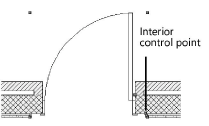
Number of Components |
Specify the number of interior wall components to wrap; when interior wall components are specified, the door enables a control point to set the wrapping point
|
|
Splay wall |
Splays the interior wall; the splay can be specified either as an angle/diagonal or with width and depth values |
|
(1) Angle |
Enter the interior wall splay angle |
|
(2) Diag |
Enter the interior wall splay diagonal value |
|
(3) Width |
Enter the interior wall splay width |
|
(4) Depth |
Enter the interior wall splay depth |
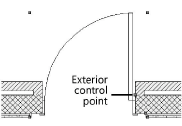
Door settings: Exterior Wall Detail pane
Exterior wall detail options are not enabled for curtain wall doors. For more extensive component wrapping and wall profile options, see Wall closure settings.
Click to show/hide the parameters.Click to show/hide the parameters.
|
Parameter |
Description |
|
Number of Components |
Specify the number of exterior wall components to wrap; when exterior wall components are specified, the door enables a control point to set the wrapping point
|
|
Splay wall |
Splays the exterior wall; the splay can be specified either as an angle/diagonal or with width and depth values |
|
(1) Angle |
Enter the exterior wall splay angle |
|
(2) Diagonal |
Enter the exterior wall splay diagonal value |
|
(3) Width |
Enter the exterior wall splay width |
|
(4) Depth |
Enter the exterior wall splay depth |
Door settings: Classes pane
The visibility of the overall 3D door is controlled by the Class setting from the Object Info palette; part settings are controlled from the Door Settings dialog box.
Click to show/hide the parameters.Click to show/hide the parameters.
|
Parameter |
Description |
|
Door parts |
To control appearance and visibility, select a class from the list of classes present in the drawing, or create a new class. Select <Door Class> to place the part attributes in the same class as the door object. For doors with an Opening Configuration, in a 3D view a no fill/no pen weight extrude completely fills the wall in place of the door; this extrude is placed in the Interior Jamb class and is filtered out in IFC export operations. Change the class settings to control the visibility of the extrude. The Pocket Door Recess class determines the Recess Finish Attributes when Pocket Door Recess Class is selected on the Configuration: Pocket pane (see Door settings: Configuration: Pocket pane). |
 Door settings: Energos pane
Doors play a critical role in energy analysis calculations. Energy is lost through any door glass, and when the door is opened, but energy is also gained by solar radiation through the door glass. Accurately determining the R-Value/U-Value and the shading factor is essential for the overall energy analysis.
Vectorworks Architect is required to conduct an energy analysis; however, energy-related parameters can be specified here for informational purposes.
Click to show/hide the parameters.Click to show/hide the parameters.
|
Parameter |
Description |
|
Include in calculations |
When selected, the door is eligible to be included in energy calculations, depending on the energy analysis settings for layer/class, element inclusion, and so on |
|
R-Value/U-Value |
|
|
Automatic Calculation |
Based on the door type, the door R-Value/U-Value is calculated and displayed. This value, along with the door shading factors, is critical for a correct assessment of the building envelope in energy calculations. |
|
Manual Input |
Select this option to override the calculated R-Value/U-Value and enter a manual value for the door instead. For complex or detailed door designs, enter results from a third-party calculation here. |
|
Door Type |
Select the thermal quality of the frame and any door glazing. Sets can be created and edited; see Specifying system sets. |
|
Shading |
Select the level of shade for each type of shading near the door, or select Custom from any of the lists. The Edit Shading dialog box opens, to manually enter a percentage for when the door is in the shade. |
|
General |
Select the general shade conditions where the door is located |
|
Surrounding |
Specify surrounding shade conditions that might affect the amount of solar radiation reaching the door |
|
Summer Shading |
Specify special shade conditions that apply in during the summer months (for example, when nearby deciduous trees shade the door) |
|
Additional Shading |
Select any mechanical or passive shading mechanisms in place, or select Custom and enter a shading percentage in the Edit Shading dialog box |
|
Summer Ventilation |
Opens the Summer Ventilation Settings dialog box, for specifying summer ventilation options for when the door is typically open. Summer ventilation options (ground floor, upper floor, night): Select the type of ventilation system usage, if any, for the door Operable opening width: For windows in doors, indicates the width of the window opening gap for an operable window (which affects the amount of ventilation) |
Door settings: Data pane
Certain data fields represent calculated values and cannot be edited; as a result, the Field Name and Field Value are grayed for those data fields.
Click to show/hide the parameters.Click to show/hide the parameters.
|
Parameter |
Description |
|
Field Name |
Select the data field from the list and its name displays beneath the list; information associated with the Field Name can be specified in the Field Value area. The user fields can include additional user-defined information with the door. |
|
Field Value |
Enter data for use in the door schedule |
