Stair settings: 2D Graphics tab
The settings on the tab can be saved as a set and then loaded, replacing the current tab parameters.
Click the 2D Graphics tab to set the stair’s 2D appearance on lower and, if desired, upper floors. The lower floor is always the floor where the stair has been placed. Selecting display options for the upper floor is optional; the upper floor representation is usually on another layer, and can be specifically selected here. These parameters do not affect the 3D appearance of the stair.
Click to show/hide the parameters.Click to show/hide the parameters.
|
Parameter |
Description |
|
2D Graphic Settings |
Saves settings so they can quickly be applied again; see Using saved sets for stair settings |
|
View |
Determines the view to apply the parameters to the stair; depending on drawing settings like layer scale and the document preference Hide details, the detailed or schematic view status is displayed |
|
Detailed |
Applies the 2D graphic parameters to stairs in a detailed layer scale view |
|
Schematic |
Applies the 2D graphic parameters to stairs in a schematic scaled view |
|
Accept for all views |
Applies the 2D graphic parameters to stairs in all views (detailed and schematic) |
|
Stair Break Settings |
Sets the stair break parameters; select the stair break configuration, and then refine the display with the additional parameters |
|
Break Elevation |
Sets the Z-height (relative to Layer Z=0) for the stair break |
|
Break Line Angle |
Specifies the angle of the break line, measured from the leading edge of the tread/riser |
|
Break Lines Separation |
Sets the distance between the pair of parallel break lines, measured in page scale units |
|
Break Line Extensions |
Indicates how far to extend the break lines past the sides of the stair |
|
Draw outlines at break |
When selected, draws boundary outlines around the stair object |
|
Show markers at break |
When selected, adds start and end markers to the walk line above and below the stair break |
|
End of Walk Line is: |
Sets the end of the walk line at either the last tread before the stair break or directly at the break |
|
2D Graphics Settings |
Controls the display of the walk line, nosing, stringers, headroom outline, and railings in Top/Plan view only |
|
Show nosing/riser offset |
Displays the stair nosing and riser offset |
|
Show tread offset |
Displays the left and right tread offset |
|
Show stringers |
Displays the stair stringers |
|
Show headroom outline |
Displays the headroom outline; specify the headroom height above the stair |
|
Show handrail |
Displays the handrail (railing parameters are set on the Railings tab) |
|
Show top rail |
Displays the top rail of the handrail and/or guardrail |
|
Show posts |
Displays railing posts |
|
Show railing above stair break |
Displays the railing above the stair break |
|
Show stair structure at lower floor |
Displays the stair structure on the lower floor in Top/Plan view |
|
Show notch at lower floor connection |
Displays the notch on the lower floor connection in Top/Plan view |
|
Show top tread |
Displays the top tread in Top/Plan view |
|
Show notch at upper floor connection |
Displays the notch on the upper floor connection in Top/Plan view |
|
Cut Graphic (on Layer [layer name]) |
The stair always displays on the lower floor (the floor where it has been placed). If an existing stair is selected for editing, the stair’s layer displays. If editing stair preferences, the active layer displays. Set the display of stair breaks, walk lines, arrow directions, and stair text. |
|
Display Stair |
Select the stair display configuration for the lower floor: Plain (no break): Does not draw a stair break; the stair is drawn as set by the 2D attributes on the Graphic Attributes tab Solid with Break: Draws a stair break; the stair is drawn as set by the 2D attributes and 2D Stair Break on the Graphic Attributes tab, but line styles remain solid Below Break Only: Draws a stair break; all geometry above the stair break is hidden Above Break Only: Draws a stair break; all geometry below the stair break is hidden Break, Dashed Above: Draws a stair break; all line styles above the stair break are automatically dashed according to the settings on the Graphics Attributes tab Break, Dashed Below: Draws a stair break; all line styles below the stair break are automatically dashed according to the settings on the Graphics Attributes tab Dashed Above Only: Draws a stair break; all line styles above the stair break are automatically dashed according to the settings on the Graphics Attributes tab Dashed Below Only: Draws a stair break; all line styles below the stair break are automatically dashed according to the settings on the Graphics Attributes tab |
|
Walk line below/above stair break |
When selected, draws a walk line below/above the stair break. For Plain (no break) Display Stair style, draws a walk line the full length of the stair. When a walk line is indicated, select whether to display a start and/or end marker on the ends of the walk line (to show markers at a break, Show Markers at Break must be enabled). Set the arrow direction. The marker style is set on the Graphic Attributes tab. |
|
Draw entire break |
For Below Break Only and Dashed Below Only, select whether to draw the top of the stair break line, in addition to the bottom of the stair break line (which is always shown) |
|
Stair Data |
Opens the Stair Data Settings dialog box, for setting the appearance of stair text on the lower floor (see Step 2) |
|
Top Graphic |
Displays the stair on the upper floor in both detailed and schematic views, and sets the display of stair breaks, walk lines, arrow directions, and stair text for the upper floor. If the stair’s Top component is used for horizontal section viewports, the default location is at the top of the railings. For stairs without railings, the default location of the Top component is 20 cm above the total rise of the stair, but that location can be changed (see Relocating 2D components of symbol definitions and plug-in objects). If you change the height of the stair, the default location is reset to 20 cm above the total rise. |
|
Upper floor stair configuration |
The Display Stair, walk line, and Stair Data options function the same as for the lower floor |
|
Break Offset |
Adjusts the position of the stair break along the walk line. Enter a positive or negative offset to position the break without any gaps between upper and lower floors. |
|
Include top graphic on upper floor |
For Top/Plan view, displays a 2D top graphic of the stair on the selected upper floor layer; select to enable Layer |
|
Layer |
Specify the layer on which to display the upper floor representation of the stair. This selection affects both the detailed and schematic display of the stair on the upper floor. It is not related to the total rise stair height selection on the General or Geometry tab. |
|
Preview |
Displays a preview of the upper and lower floors of the 2D stair with the parameters applied |
Click Stair Data for the lower, and optionally, the upper floor, to set the display of the 2D stair information text.
The Stair Data Settings dialog box opens. The stair configuration determines the number of available run or flight parameters. The appearance of stair data text is set on the Graphic Attributes tab.
Click to show/hide the parameters.Click to show/hide the parameters.
|
Parameter |
Description |
|
Show Numbers of Risers |
When selected, displays the riser numbers for the stair. Specify the text position and offset for the flight and the step, and set the text rotation. |
|
Position in flight |
For straight stairs, indicate whether riser numbers display on the center, left, or right of the flight. For other stairs, indicate whether riser numbers display centered, or on the inner or outer side of the stair flight. The Offset value sets the distance between the riser numbers and the stair boundary. |
|
Position in step |
Sets the riser position centered on the step or at the start of the tread. The Offset value sets the distance between the riser numbers and the start of the tread, for numbers at the start of the tread only. |
|
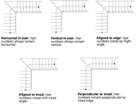
Rotation |
Specifies the rotation of the riser numbers
|
|
Run |
For each available run of stairs with multiple flights, select whether to include text for the arrow direction (Up or Down, depending on walk line direction), total rise, number of risers, average riser height, average tread depth, walk line length, and/or line break. As each item is selected for display, its code appears in the text box; text can also be typed between items. Select Line Break to add a carriage return between items. Set the angle of the text. |
|
Note |
For the entire stair, select whether to include text for the arrow direction (Up or Down, depending on walk line direction), total rise, number of risers, average riser height, average tread depth, and/or walk line length. As each item is selected for display, its code appears in the text box; text can also be typed between items. Select Line Break to add a carriage return between items. Set the angle of the text. |
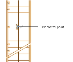
The position of the stair run and note text can be adjusted by moving its control point.