 Creating a pathway or boundary modifier
|
Mode |
Tool |
Tool set |
|
Pathway Path Boundary Path
|
Site Modifiers
|
Site Planning |


The path modifier creates a surface defined by one longitudinal profile and a set of transverse profiles, with the path defined as:
a polyline with a width value (the polyline is the center line) in Pathway Path mode, or
a polyline as a boundary (with a generated center line based on the boundary) in Boundary Path mode. The center line remains defined within the bounds of the area of the modification defined by this object.
After drawing the path, shape the modifier by editing the center path (longitudinal profile) and by adding as many transverse profiles as needed. To edit the longitudinal and transverse profiles, view each profile section in an editing mode. The profile section displays the overall length of the profile, with vertices on each elevation change. Interactively add vertices and change the elevation and grades of existing points, snapping to existing geometry when Show other objects while in editing modes is selected in the Vectorworks preferences.
The modifier can be applied to the existing or proposed site model; the site model is modified when the site model is updated. Draw a path with the Site Modifiers tool, or draw a polyline and then select the Create Objects from Shapes command to change it to a pathway path or boundary path modifier (see Creating objects from shapes).
To create a pathway path or boundary path modifier:
Click the tool and mode.
Select the polyline creation mode; see Polyline tool.
Click to set the modifier object’s start point.
Click to set the end of the segment and the beginning of the next. Continue drawing segments in this manner until the path is complete. Return to the start point (for boundary configuration), or simply double-click to finish creating the modifier path.
In Pathway mode, the Site Modifier: Pathway Mode dialog box opens. Specify the width of the path modifier.
In Top/Plan view, add transverse profiles to the path as needed by clicking Add Profile from the Object Info palette, and then clicking on the modifier to create a profile at that location.
From the Object Info palette, edit the longitudinal and transverse profiles as needed to shape the modifier. Change the location of the modifier with the Reshape tool (see Reshaping the modifier path or boundary) or through the Object Info palette.
In Top/Plan view, click the drop-down context menu to access editing commands.
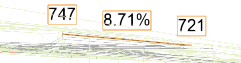
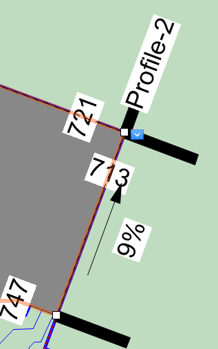
In object editing mode, adjust the profile's elevation and grade
Normally, create grade limits around the modifier. The parameters can be edited from the Object Info palette.
Click to show/hide the parameters.Click to show/hide the parameters.
|
Parameter |
Description |
|
Simplification Tolerance |
Enter a positive value to redefine the horizontal distance between the closest parts of two neighboring portions of the modifier. A longer distance simplifies the modifier polygon, reducing the number of source points that modify the site model. A shorter distance increases the number of source points that modify the site model. A value of 0 (zero) does not simplify the modifier. |
|
Modifier Vertex Count |
Displays the number of vertices created by the site modifier to modify the site model |
|
Apply To |
Specifies whether the site modifier applies to the existing or proposed site model |
|
Update Site Model |
Updates the site model with any site model modifications that have occurred. If the update causes the site model contours to fall outside the minimum/maximum elevation range specified in the site model settings, an alert displays, allowing the range to be adjusted. |
|
Configuration |
Indicates the type of modifier object |
|
Show the surface in 3D |
In 3D views, represents the modifier with a 3D mesh. This is convenient when working with a modifier independently of a site model, or when it's helpful to view the site modifier on the surface of the site model in 3D views. Deselect the option to view only the effects of the modifier on the site model. |
|
Vertical sides for inner modifiers (closed modifiers only) |
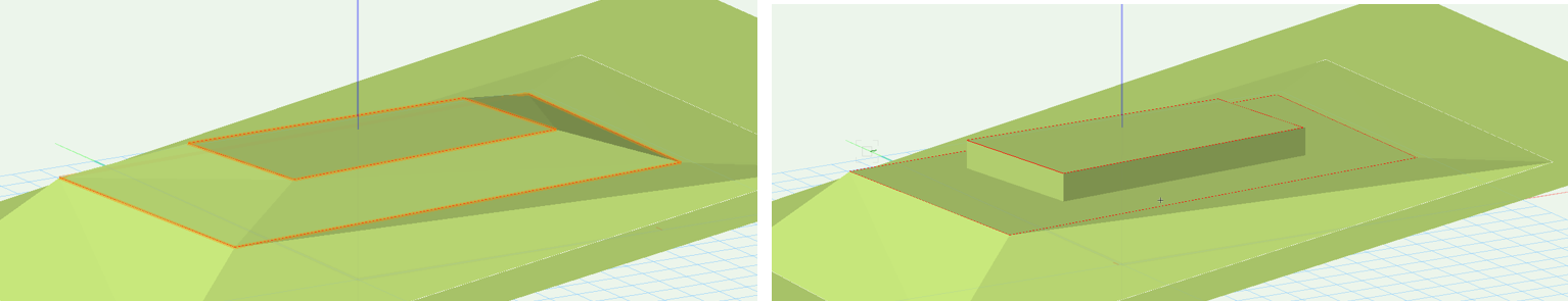
Determines whether inner modifiers create a transitional surface (when deselected) or a vertical retaining edge (when selected)
Vertical sides for inner modifiers deselected (on the left) and selected (on the right) |
|
Longitudinal Profile |
Define the elevation changes along along the path modifier, and set the profile appearance |
|
Edit Profile |
Enters editing mode for the selected profile, for Editing aligned hardscapes or modifiers with profile lines |
|
Start Elevation End Elevation |
Enter the starting and ending elevation of the modifier; alternatively, enter one of the elevations and enter a Slope value to automatically calculate the other elevation |
|
Slope |
Enter the slope value; alternatively, when the Start Elevation and End Elevation are entered, the slope displays |
|
Realign Elevations |
If changes occurred to an elevation, resets the affected vertex elevations |
|
Fit to Surface |
Conforms the longitudinal profile line to the surface of the site model |
|
Profile Line Class Profile Text Class |
Select <Site Modifier Class> to place the profile in the same class as the modifier; select a class, or create a new class, to control profile line appearance and visibility |
|
Elevation Marker |
Select the elevation indicator type |
|
Elevation Marker Factor |
Specifies the scale factor of the elevation marker |
|
Slopes Grade Def |
Determines the how the Slope is calculated and displayed |
|
Show profile line |
Toggles the display of all profile line parameters (name, slope, elevation, and markers) |
|
Show profile names |
Toggles the display of the profile names |
|
Show slopes |
Toggles the display of all slope values |
|
Arrow indicates downward |
When Show slopes is selected, adds an arrow to indicate which side slopes down |
|
Show vertex elevation |
Toggles the display of all vertex elevations |
|
Show profile line markers |
Toggles the display of markers at the ends of the profile line |
|
Profile Line Marker Styles |
Opens the Set Marker Style dialog box, to select the profile marker type at each end of the profile line; markers can be the same (Match beginning) or different (Differentiate) at each end of the section line |
|
Transverse Profiles |
Transverse profiles are always perpendicular to the center line; define the elevation changes along each transverse profile and set the appearance |
|
Profile |
Scrolls through the profiles, highlighting the selected one; click the center button to highlight the current profile |
|
Name |
Displays the name of the currently selected profile |
|
Profile Line Class Profile Text Class |
Select <Site Modifier Class> to place the profile in the same class as the modifier; select a class, or create a new class, to control profile line appearance and visibility |
|
Slopes Grade Def |
Determines the display of the slope units |
|
Show profile lines |
Toggles the display of all profile line parameters (name, slope, elevation, and markers) |
|
Show profile names |
Toggles the display of all profile names |
|
Show slopes |
Toggles the display of all slope values |
|
Arrow indicates downward |
When Show slopes is selected, adds an arrow to indicate which side slopes down |
|
Show vertex elevation |
Toggles the display of all vertex elevations |
|
Show profile line markers |
Toggles the display of markers at the ends of the profile line |
|
Add Profile |
Adds a profile line for modifying the surface |
|
Edit Profile |
Enters editing mode for the selected profile, for Editing aligned hardscapes or modifiers with profile lines |
|
Profile Line Marker Styles |
Opens the Set Marker Style dialog box, to select the profile marker type at each end of the profile line; markers can be the same (Match beginning) or different (Differentiate) at each end of the section line |
|
Delete Profile |
Deletes the selected profile |
|
Information |
|
|
Update Calculations |
Updates the area and volume calculations displayed in the Object Info palette for the area of the site model located under the site modifier (grade limits must exist around the modifier) |
|
Site model area and volume data |
Displays the area and volume information for the site model area located under the site modifier; select the units for the area and volume (grade limits must exist around the modifier). For more information, see Site model properties. |
|
Vertex parameters |
Edits the path vertices; see Editing vertex-based objects |
|
Move |
Select the vertex, and then edit its X/Y value |
|
Edit |
For vertex selection made in Move, scrolls through the vertices, highlighting the currently selected vertex. Click the center button to highlight the selected vertex. |
Reshaping the modifier path or boundary
|
Mode |
Tool |
Tool set |
|
2D Boundary
Longitudinal Profile
|
Reshape
|
Basic |
Two extra modes are available when both the Reshape tool and a path modifier are selected in Top/Plan view. See Reshaping objects.
The 2D Boundary mode reshapes the boundary polyline of a boundary path modifier.
The Longitudinal Profile mode reshapes the longitudinal profile of either the pathway or boundary modifier.
