Inserting grade objects
|
Mode |
Tool |
Workspace: Tool set |
|
Insert
|
Grade
|
Architect and Spotlight: Building Shell Landmark: Site Planning and Dims/Notes |


To insert a grade object:
Click the tool and mode.
Click to set the start of the grade. Move the cursor and click again to set the end point.
If connecting the grade object to another grade object, forming a network, the existing grade object is highlighted.
The Grade Settings dialog box opens. Click the Object Properties tab and enter the desired settings.
Click to show/hide the parameters.Click to show/hide the parameters.
|
Parameter |
Description |
|
General |
Given two parameters, the grade parameters are calculated for the remaining parameters. Enter the two known parameters to calculate and display the other grade parameters. The initial elevation of the first and/or second points of the grade object is determined by these methods: If an existing grade object is under one of the points, the elevation of the existing grade object is used. If a stake object is under one of the points, its elevation is used. If a site model is under one of the points, the calculated elevation of the point is used. If none of the above occurs, the elevation of the last created grade object is used. |
|
Parameter 1 |
Select the first known parameter (Elevation 1, Elevation 2, Downward Grade in %, Upward Grade in %, Downward Ratio (rise/run), Upward Ratio (rise/run), or elevation change) and enter the value associated with the parameter |
|
Parameter 2 |
Select the second known parameter (available choices depend on the first parameter selected), and enter the value associated with the parameter |
|
Parameter Display |
The remaining parameters are calculated and displayed, including the grade length |
|
Graphics |
Sets the graphic appearance of the grade object. The appearance of the indicator, grade definition, and precision is set in the global settings (see Specifying global grade object preferences). Once created, each graphic element of the grade object has its own control point. Move a control point to adjust the position of the text and indicator.
|
|
Elevation marker symbol |
Click the elevation marker symbol selector to select a resource from the Resource Selector. The marker appears at each end of the grade object. |
|
Scale |
Scales the elevation marker with respect to the layer scale by the specified scale factor; a Factor of less than one decreases the size of the marker while a Factor of more than one increases its size |
|
Show slope value |
Displays the grade value. If the value does not display, increase the text size by selecting Text > Size. |
|
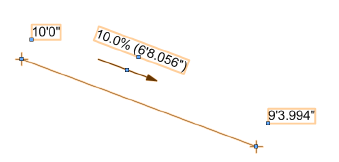
Show projected/surface length value |
Displays the projected grade length/surface length and the slope arrow; the slope arrow always indicates the downward slope direction. Enter a prefix for the value, if desired. The projected length is the distance between the points as measured along a horizontal projection; the surface length is the distance between the points as measured along the surface, which facilitates a more accurate calculation for purchasing estimates. If both Show projected length value and Show surface length value are selected, both values are displayed along the grade object, with a slash (/) between them (prefix + projected length/prefix + surface length). |
|
Show length value(s) below arrow |
When Show projected length value and/or Show surface length value is selected, displays the value below the slope arrow |
|
Show elevation value |
Displays the elevation value at each end of the grade object |
|
Draw line |
Draws a slope line to represent the distance between the two elevation points |
|
Site Model |
|
|
Grade Object Mode |
|
|
Use grade object heights |
Uses the elevation values specified in the General parameters |
|
Use heights from site model |
When the grade is drawn over a site model, the elevation of the first and second points is derived from either the existing or proposed site model. The values in the General parameters do not apply. The grade object updates with the site model. |
|
Change site model (use grade as pad modifier) |
Uses the grade object as a site modifier object; the elevation values specified in the General parameters are applied to either the existing or proposed site model. Update the site model to apply the changes (select the site model and click Update from the Object Info palette). |
|
Apply To |
|
|
Existing/Proposed site model |
Selects the site model to provide elevation values when Use heights from site model is selected, or the site model to be modified when Change site model is selected |
Grade objects can be edited from the Object Info palette. Commonly-required parameters can be accessed directly from the Object Info palette, or click Settings to change any of the parameters of selected grade objects. Alternatively, edit the settings of a grade object by double-clicking on it, or right-click on a grade object and select Edit from the context menu.
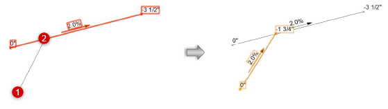
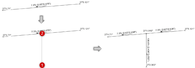
Grade objects can be connected to form a network. Either move the endpoint of one grade object onto another grade object, or create a new grade object with an end point on an existing grade object. The existing grade object is split at the new endpoint, creating a network of overlapping grade objects. The elevation of the shared point is interpolated from the slope of the existing object; if an elevation point is updated, all overlapping grade objects automatically update. Click Update mode from the Tool bar of the Grade tool to force an update of all overlapping grade objects.
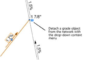
When grade objects are connected in a network, they move as one object and all elevations adjust accordingly. Detach a grade from its network, making it an independent grade object, by selecting Detach from Grade Network from the drop-down context menu.