 Quick Start: Let's create a site model
Difficulty level: Intermediate
With a few clicks, you can create a simple site model and add site modifiers and objects to it. Use this topic to help you understand how to draw in Vectorworks, import source data to create a simple site model, modify it, place objects, view objects, and to get used to the interface. This conceptual terrain is just an idea of how actual site models are created and modified, but it will help you get going!
The location of commands and tools varies, depending on the workspace. You can learn to use the Quick Search feature to quickly find commands or tools; see Quick Search. You can also look at the Commands and tools PDF here in the Vectorworks help system.
Create the site model
A site model is usually based on source data, perhaps from a surveyor or from an imported site file. Source data can originate from a survey file of tabulated data points, 3D loci, polygons, polylines, or stake objects, or an imported file containing those objects. You can even obtain source data from a point cloud.
We're going to import a file containing source data from another application. Download the file named Elevation data.dwg available here, saving it to your computer. Since this file uses metric units, we're going to work in the metric system.
Select New to open a new, blank file.
The drawing opens in Top/Plan (2D) view, centered on the internal origin.
Select Units to open the Units dialog box. On the Dimensions pane, select Meters for the Length Units and Square Meters for the Area Units.
Select Import Single DXF/DWG, and choose the Elevation data.dwg file that you downloaded earlier.
Notice that Vectorworks automatically detects that meters were used for the units in the file. Accept the defaults.
If the Font Mapping dialog box opens, accept the replacement font. Import the file.
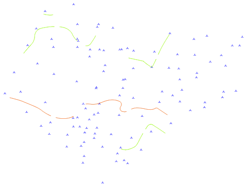
We will use this imported site data to create the site model
You have imported a set of 3D loci and 3D polygons which contain elevation data. These were automatically sent to a new design layer named after the file: Elevation data. Normally, you do want the site model in its own design layer; the site model should be centered on the internal origin.
Similarly to a real world situation, we need to do a little cleanup on the data. In this example, we only want to use the loci, and remove the 3D polygons; based on their name, the 3D polygons come from contours in the original file. Additionally, they contain a lot of vertices, which is not ideal.
Sometimes you may receive, and need to use, a combination of 3D polygons and loci, or all loci, or all 3D polygons; it depends on the file.
Click the Select Similar tool  , and click on a 3D polygon. This selects all of the polygons.
Press the Delete key.
Let's check that the loci we have are valid data. Click the Select Similar tool  , and click on a 3D locus to select all of them.
Select Validate 3D Data.
We have some duplicate data points, which can cause issues when creating the site model. Vectorworks can delete them for you; click Delete Points.
With the 3D loci still selected, select Site Model from Source Data. The Site Model Settings dialog box opens automatically.
There are two ways to display a site model: existing and proposed. Existing represents the site before any modifications occur. The proposed site model is the existing site model, plus the geometric effects of site modifiers. We want to see the version of the site model where we plan to make various modifications — the proposed site model.
On the 2D Display and 3D Display panes of the site model settings, select the Proposed Only Display. Select a 2D Display Style of 2D Contours and a 3D Display Style of 3D Mesh.
On the 2D Display pane, display contour labels for major contours only, and make them parallel to the topo line, which is standard.
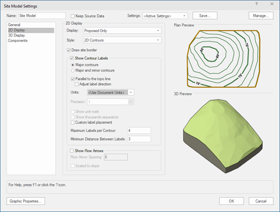
2D Display settings
Accept the remaining default site model settings, and click OK to create the site model.
The text of the contour labels is too large in relation to the site model. Select Size from the Text menu, and choose a font size of 6.
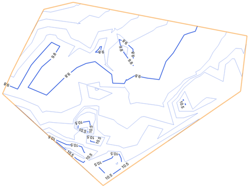
Top/Plan view of the site model
On the View bar, select Right Isometric from the Current View/Standard Views list, or just press 3 on your numeric keypad or use the Onscreen View Control cube to switch to that 3D view.
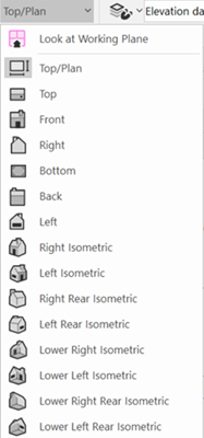
Use the Onscreen View Control cube or the Flyover tool  to view the 3D model from various angles. If you hover the cursor over the site model, you can see the triangulation between the data points, which creates the site model surface.
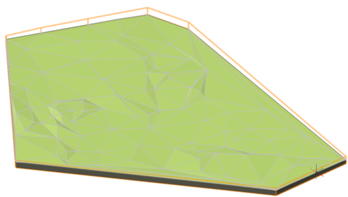
Here is the proposed site model in a 3D view
Adjust the triangulation
Sometimes, the source data requires adjustment after the site model has been created. If we focus our attention to some of the contours at 10.5 m, we recall from visiting the actual site that the these contours don't perfectly represent the elevations. This can occur when the elevation points from the survey are rather sparse.
We can go back to the source data and add (or remove) loci or 3D polygons at the proper elevation to make any needed corrections.
Click Quick Preferences Settings and ensure that the Quick Preferences setting for Show Other Objects While in Edit Modes is enabled.
![]()
Switch to Top/Plan view by selecting it from the Current View/Standard Views list on the View bar, or by pressing 0 on the numeric keypad.
Select the site model, and from the Object Info palette, click Recreate from Source Data to enter object editing mode. An alert warns you about losing contour edits or surface sculpting, but we haven't made such edits, so we can dismiss this alert.
We can still see the Top/Plan view of the site model in the editing mode, which is very helpful. We want to stay in Top/Plan view, so we will stick with a 2D tool to make edits. Click the 2D Polygon tool  , click to draw a line connecting two of the 10.5 m areas at the bottom of the window, and double-click to finish.
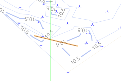
Draw a polygon between the two areas at 10.5 m
We need to set an elevation for the selected line, so we have to convert it to a 3D polygon. Select Convert to 3D Polys. In the Object Info palette, enter an elevation of 10.5 m for the Z height. Exit the editing mode by clicking Exit Recreate from Source Data.
If you're not in Top/Plan view, return to Top/Plan view by selecting it from the Current View/Standard Views list on the View bar, or by pressing 0 on the numeric keypad or using the Onscreen View Control cube.
The triangulation of the source data was adjusted by the 3D polygon.
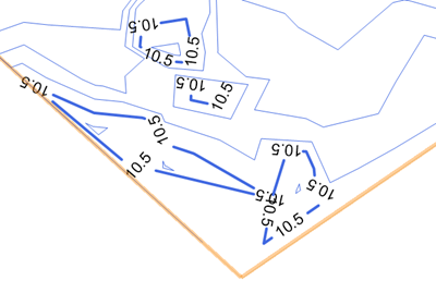
We've adjusted the source data
Add site modifiers
Now that the site model is ready, it's time to make edits to the proposed site model. We're going to create a flat area for a nice garden spot.
First, we need to establish the area of the site model where edits are permitted by drawing a grade limit. Beyond the grade limit, the site model remains undisturbed. The grade limit transitions from the proposed site model to the existing site model.
Click the Site Modifiers tool  and click Grade Limits mode
  . Draw the grade limit area between the 10.5 m contours.
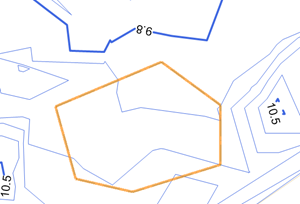
Establishing the work area with grade limits
Let's add a slightly raised, flat area for the garden. If needed, zoom in on the area by scrolling with your mouse wheel. Click the Site Modifiers tool  and click Planar Pad mode
  . Draw a rectangular shape to create the planar pad within the grade limits.
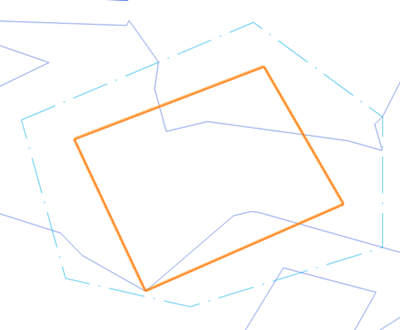
Planar pad for the garden
In the Object Info palette, set an Elevation for the pad modifier, of 11 m.
Update the site model by clicking Update Site Model from the Object Info palette. Now the proposed site model is modified by the pad, within the limits set by the grade limits area. Note how the grade limits define the gradually changing area of site model changes. Use the Onscreen View Control cube or the Flyover tool  to look at the pad in a 3D view.
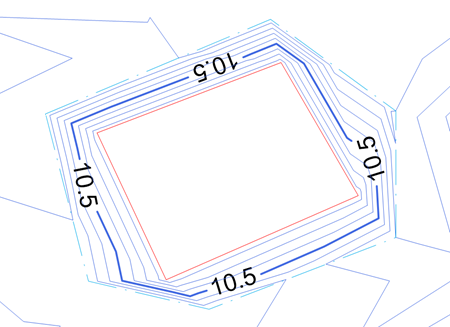
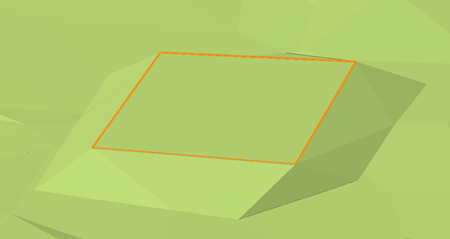
Top/Plan and 3D view of the modified site model
Select the site model. In the Object Info palette, click Update Calculations. You can see that if we wanted to add this raised garden area, we'd need to add about 60 cubic meters (or 2,000 cubic feet) of fill volume to the site.
Adding site objects
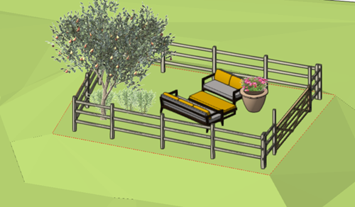
Let's add plants and a seating area to the garden, and then a fence.
Let's add a tree and some shrubs to the planar pad. Click the Plant tool  . From the Tool bar, click the Plant Style list, and choose the Plant Basic Ornamental Tree 01 from the Resource Selector.
Place a tree on the pad. The tree is automatically placed on the surface of the site model.
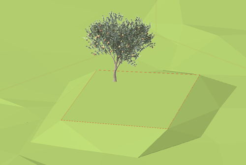
We planted a tree in the garden
Now choose Plant Basic Low Shrub 01 from the Plant Style Resource Selector. Place a few shrubs around the base of the tree.
Open the Resource Manager (Ctrl+R (Windows) or Cmd+R (Mac)) if it's not already open. In the Resource Manager, search for the term "layout." Select the "Site layout - Patio couches with planter" layout symbol, and place it in the garden area. Because we're in a 3D view, the symbol is placed on the surface of the site model.
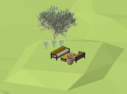
We've added a comfortable place to sit
Switch to Top/Plan view by selecting it from the Current View/Standard Views list on the View bar, or by pressing 0 on the numeric keypad. (You can place a fence in a 3D view as well, but it's easier in Top/Plan view). Add a fence around the perimeter of the garden area. Click the Fence tool  ; from the Tool bar, click the Fence Style list, and select the Fence Wood Split Rail symbol (metric) from the Resource Selector.
Click to start drawing the fence, and click at each corner of the pad to place the fence. The fence is automatically placed on the surface of the site model.
Press 1 on the numeric keypad (or use the Current View/Standard Views list) to obtain Left Isometric view.
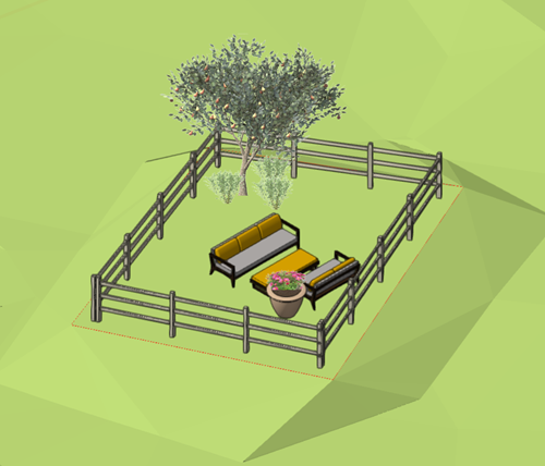
A fence will keep deer away from the garden
We need a gate to get in and out of this relaxing garden spot. Select the fence, and click the Reshape tool  . Click Gate Mode
  and Add Gate mode
  , and select a gate from the Gate Configuration Resource Selector. A gate to match the fence is already suggested. Click on one of the fence's panels to place a gate in the fence.
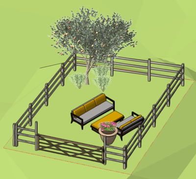
Looks like a nice place to relax!
