 Curb preferences
These settings are available in the following locations:
Curb Preferences dialog box (creating an object)
Curb Settings dialog box (editing an object)
Object Info palette (editing an object)
Curb Style dialog box (creating or editing a style)
If a style is selected, only parameters set by instance can be edited (see Concept: Plug-in object styles). Instance parameters can be set independently for each instance of the object in the drawing.
Additional plug-in object settings for the 2D components and cut plane display are available; see Additional plug-in object style and instance options.
Curb preferences: Overall
Click to show/hide the parameters.Click to show/hide the parameters.
|
Parameter |
Description |
|
Curb Style |
Opens the Resource Selector to select a resource for placement. |
|
Convert to Unstyled |
If Use Style is currently set to a style, select this option to convert the object to unstyled; the current values are retained, but all parameters are set to By Instance to allow editing |
|
By Style/Instance |
A graphic indicates whether each parameter is set to By Style and given a fixed value or set to By Instance and editable in the dialog box. An object style may have a combination of both settings, to balance the need for consistency and flexibility. By Style/Instance settings are established by the style and cannot be changed from the settings dialog box.
To edit the object style, see Editing plug-in object styles; editing the style modifies all plug-in objects in the file that use the style. |
|
3D Preview |
Dynamically displays a 3D preview of the curb with the currently selected parameters |
|
View |
Select the standard view for the 3D preview |
|
Render |
Select the render mode for the 3D preview |
|
Name Formula (Curb Style dialog box only) |
Enter the primary name of the curb style in the center field, and optionally select a prefix and/or suffix to autopopulate the style name based on the selected parameter values. For example a Name Formula of [Prefix=ID] [Main Name manually entered as "Cobblestone Curb with Gutter"] [Suffix=Category] might display as SE6 Cobblestone Curb with Gutter Paving Border in the list of curb styles available for use. See Creating plug-in object styles for more general information about creating a plug-in object style. |
Curb preferences: General pane
Click to show/hide the parameters.Click to show/hide the parameters.
|
Parameter |
Description |
|
Class |
To control appearance and visibility, select a class from the list of classes present in the drawing, or create a new class; if this parameter is set by style, all instances using this style are assigned to this class. |
|
Category |
Optionally, select a curb category, or select Manage Custom Categories to edit the list. From the Manage Custom Categories dialog box, click Add or select a list item and click Edit, and then enter a new name. Select a list item and click Delete to remove it from the list of available categories. If a curb category is specified, it can be used in the instance or style name formula. |
|
Curb Type |
Enter a name for the curb type, as you would refer to the style in design terms, not specifications. This can be used as part of the instance name formula; Vectorworks-provided curb styles use this name as the root of the style name. |
|
ID |
Optionally, enter an ID for the curb. If an ID is specified, it can be used in the instance or style name formula. |
|
Instance Name |
Select whether to manually enter a name for this instance or to use a name formula. For Manual, enter a name. For Instance name formula, select a name formula from the list of name formulas present in the drawing. Select Manage Custom Name Formulas to add, edit, or delete a name formula from the list; see below. |
|
Draw |
|
|
Draw 2D |
Select the level of detail for representing the curb in Top/Plan views. Draw the curb as a simple line, with different line types representing the front and back lines, or with full detail. |
|
Draw 3D |
Select the level of detail for representing the curb in 3D views. Hide the curb in 3D, draw it in a simplified view, or with full detail. Many curbs drawn in full detail can impact performance; use a simplified view during the design phase. |
|
Vertical Insertion Offset |
Enter a vertical offset from the style's insertion point. A positive value moves the curb upward. |
|
Place Inside or Outside of Associated Object's Edge |
For curbs associated with a hardscape or landscape area, select to place the curb inside the hardscape's boundary, or outside the boundary (adding to the footprint). The front edge of the curb's main component is always aligned with the edge of the associated object. Changing this setting flips the position of the entire curb object, including any haunching, relative to the associated object. |
|
Elevation Point Frequency |
Curbs that aren't associated with another object can sample the elevation from a site model and from other 3D objects, depending on the Apply Send to Surface by Class settings. At each elevation point, a vertex is added to the curb, setting the curb's elevation at that point. Enter the distance between sampling points. Normally, each point with a new elevation creates a vertex along the curb's path. Shorter distances increase the smoothness of the curb, while increasing the distance between sampling points can avoid having too many curb segments along uneven ground. If no frequency distance is specified, only the elevation of the corner vertices affects the elevation of the curb. Vertices can be added, moved, or deleted with the Reshape tool. |
|
Apply Send to Surface by Class |
Opens the Select Classes dialog box, to determine which classes of objects to include for sending the curb to the surface of objects. Classes with a check mark in the Use column are included, and objects in those classes are valid when the curb is sent to the surface. Curbs are never sent to the surface of site modifiers, plants, or existing trees. |
Adding or editing an instance name formula
To create or edit a name formula for a curb instance:
On the General pane of the Curb Preferences or Curb Settings dialog box, select Instance name formula for the Instance Name.
In the list of name formulas, select Manage Custom Name Formulas to open the Manage Custom Instance Name Formulas dialog box.
Click Add, or select a name formula from the list and click Edit.
To delete a name formula from the list, select it and click Delete.
The Add/Edit Custom Instance Name Formula dialog box opens.
Click to show/hide parameters.Click to show/hide parameters.
|
Parameter |
Description |
|
Name |
Enter the formula's display name, for use in the list of name formulas |
|
Name Definition |
Displays the name formula, which can consist of selected name components and manually entered characters |
|
Name Component |
To add a name component to the name formula, select it from the list, and then click Add. The component is added to the end of the Name Definition. |
|
Integer/Lower-case character/Upper case character |
If Incrementing Value is selected for the Name Component, before clicking Add, select whether the value should be numeric, or a lower-case or upper-case letter. Enter the Start Value and Increment. For incrementing values to function, the Instance Name parameter must be set by style. |
Curb preferences: Specification pane
Click to show/hide the parameters.Click to show/hide the parameters.
|
Parameter |
Description |
|
Specify components as a group/Specify individual components |
Select whether to group the sustainability, permeability, and other notes as a whole for the entire curb, or whether you want to individually specify these options for each component of the curb (advanced). If specifying as a group, enter the the specifications. If specifying for individual components, you will need to add the information separately for each component. Extrude components are set in the Path Extrudes pane, while 3D symbols used in the curb require an attached record including the specifications. |
|
Description |
Optionally, enter descriptions of the curb, and of the joint/joint mortar. The descriptions can be long, such as a specification, or short. If short, the curb description can be used for the suffix in a curb style name formula. |
|
Permeability |
Includes permeability settings for the curb |
|
Permeable/Non-permeable |
Select whether the curb is permeable or non-permeable. |
|
Runoff Coefficient |
Enter the runoff coefficient |
|
Sustainability |
Includes sustainability data for the curb |
|
Metric Framework |
The current metric framework, habitat type, and the habitat type's metric value display. To change these values, click Select Framework; the available habitat type options change depending on the selected Metric Framework. |
|
Solar Reflectance Index (SRI) |
Enter the solar reflectance index value |
|
Unit Price |
Specifies a general unit price (for indicating the price in worksheets) |
|
Price Code |
Enter the price code (such as a SKU number) |
Curb preferences: Path Symbols pane
If 3D symbols are used to create all or part of the main curb object, specify the symbol settings here. Symbols used for corners and insertions are not set up on this pane.
Click to show/hide the parameters.Click to show/hide the parameters.
|
Parameter |
Description |
|
Curb configuration/Border configuration |
Select whether the curb is calculated based on radius statements (curb configuration) or uses the same symbols for the whole path (border configuration). Select Curb configuration if the curb is a single row of symbols, but the symbol changes according to the curves of the path. Curb configuration is typically used along roadways or to creating edgings like pool copings. Select Border configuration if the curb consists of multiple separate runs of border paths, side by side, with their own individual symbols, offsets, and placement calculations. The available options change depending on the selection. If there are any rows in the list for a configuration type, you cannot switch configurations; delete all rows from the list in order to change configurations. |
|
Curb configuration |
Allows creation of a curb comprising a single row of symbols, which are fit to the path according to radius statements. For example, you can specify different symbols to use for curves of different radii, and different turn directions. As the curb follows its path, the appropriate symbols are automatically applied. For preliminary or simple designs, you can specify only a straight path symbols; all segments of the curb use that symbol.
|
|
Specify the statements based on |
Select whether the path statements are defined by the radius interval's beginning, or end, or both, or select Automated Fit to start the interval at the default symbol radius and continue to the next symbol. If only the beginning is selected, the statement interval continues until the following consecutive statement. For statements using only the beginning value, the last statement row always allows for a final end value to close the last interval. Any path radii without a path statement automatically use the symbol specified for a straight path. |
|
Path statement list |
Select <New Path Statement> to add a row and make it active; set up the statement below. To edit a statement, select it in the list. |
|
Selected Path Statement |
|
|
If Path is |
For each path statement, select whether it is a straight segment or a left (external) or right (internal) radius. All curbs should have a statement for a straight segment; all radii not covered by a statement default to the straight segment symbol selection. If the path statement is based on Automated Fit, the path segment shape/direction and start value for the radius range are automatically set after you select the symbol. |
|
Start and end values for the radius range |
For radius-type paths enter the start value and, if the statements are based on the end of an interval, the end value for the radius range |
|
then Use Symbol |
Opens the Resource Selector to select a symbol to use for path segments with the specified segment type and radius values |
|
Paver Joint Width |
Enter the joint width, measured at the insertion line |
|
Delete Path Statement |
Deletes the selected path statement from the list |
|
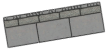
Border configuration |
Allows creation of multiple side-by-side rows with different symbols, mixed rows of symbols (mix row), offsets, and settings.
This border configuration curb has three rows. The top row is a mix row with two components |
|
Row list |
Select <New Row> to make it active, and select a symbol below. After the first row, click one of the Row Offset from Insertion Point options. To edit a statement, select it in the list. Row #: Displays the row order in the border; click in the column and drag a row to change the order. Symbol Name: Displays the name of the selected symbol for the row. Mix rows display the symbol names for each row component. Row Offset from Insertion Point: Displays the offset value from the parameter below. Ratio: For the components of mix rows, enter a number in each row to indicate the ratio of that component in the row relative to the others. Max No. Sequential Pavers: For the components of mix rows, optionally enter a maximum number of that component that can be placed in a sequence before another component is placed. |
|
Convert to Mix Row |
Allows the use of multiple symbols in the selected row. Select a regular row, and click to change it to a mix row; the row's Symbol Name changes to Mix Row, and multiple components display beneath the mix row in the list. Click each component row, and define it by selecting a symbol, and editing the options in the Selected Row section below and in the list browser. If you delete component rows, so there is only one remaining, the mix row reverts to a regular row. |
|
Add Mix Row |
When a mix row, or a component row of a mix row, is selected, adds an additional component to the mix row |
|
Selected Row |
Select each item in the row list, and use the options below and in the list to define the row |
|
Row Offset from Insertion Point |
Select how to offset the row from the insertion point, and enter an offset value |
|
(Symbol) |
Opens the Resource Selector to select a symbol to use for the row |
|
Paver Joint Width |
Enter the joint width, measured at the insertion line |
|
Row Starting Offset (%) |
To stagger the start of each row and avoid running joints, enter an offset percentage |
|
Maintain starting offset for each segment |
Applies the starting offset to each segment of the curb; if deselected, placement continues without consideration to corners |
|
At Corners, Treat All Rows as |
Select whether to treat all the rows in the border as a group when a corner is reached, or as individual rows |
|
Delete Row |
Deletes the selected row from the list |
Curb preferences: Path Extrudes pane
If extrudes are used to create all or part of the curb, manage the extrudes and their 2D profiles here.
Click to show/hide the parameters.Click to show/hide the parameters.
|
Parameter |
Description |
|
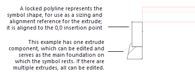
Extrude components list |
Lists the components that make up the extrude portion of the curb. Double-click <Add Extrude Component> to select a 2D symbol to provide the starting geometry for an extrude profile; a symbol added this way just serves as a starting point for the profile and does not become part of the curb. Main Component: The curb's main component sets the bottom site modifier and determines the vertical lines for the edge modifiers. If a symbol is used for the curb, it is typically used as the main component. However, if an extrude should be used as the main component, because a symbol isn't used or as an override of the symbol's designation, place a check mark in the column to select which component to use. Component Name: Displays the names of the components. Main Foundation: Place a check mark in the column to select the extrude on which all other extrudes and symbols will be directly placed. Each starting 2D symbol can only consist of one profile; however, you can have as many profiles as needed. You can also split a profile after it's added to the curb. |
|
Edit Extrude Components |
Click to enter object editing mode for the group and edit the components (see Object editing mode). Guidelines for editing curb components include: 0,0 is the insertion point for the curb, so all components should be aligned correctly with that position. If there are 3D symbols in the curb, their bounding boxes are visible to help with alignment. The curb's main component geometry should be placed to the left side of the insertion point (0,0) for easier and more consistent placement. You can create edge modifiers by placing a 2D locus on each of the main component sides. This will create modifiers along the whole curb, which will then affect the site model grade. As the two edge modifiers are independent of each other, you can create different elevations for the front and rear edges. If you add a line profile, it displays as a separate item named Foundation Line in the extrude components list. If Specify Individual Components is selected on the Specifications pane, you can also set specifications for each component in the Object Info palette while in object editing mode. You can set a material for each individual profile via the Object Info Palette. The 2D attributes must be set in the attributes pane. Make sure the main component is sent to the front, so it will be the top curb component in Top/Plan view.
|
|
Delete Extrude Component |
Deletes the selected component |
|
Extrude Configuration |
Select how the geometry should be built for each segment of the curb; extrudes don't always act as expected, depending on the profile shape and path, which may twist or realign. You may need to try different configurations to determine which works best in each case. |
|
Curb Ends |
Select whether the curb ends should be vertical or perpendicular to the curb path |
|
Use bottom modifier (cut into site model) |
Applies the bottom modifier, which is placed at the bottom of the main component; this lets the curb cut into the site model |
|
Use edge modifier |
If a bottom modifier is used, the curb can also use modifiers at the edges of the main component for a smooth transition to the site model at the edges of the curb |
|
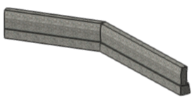
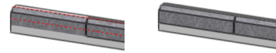
Show modifier edge |
If edge modifiers are used, displays the modifier edge
Modifier edge shown (left) and not shown (right) |
Curb preferences: Corner Configurations pane
A curb can have as many different corner configurations as needed, including multiple 3D symbols and specified cuts. You can set up if-then statements to automatically use the appropriate symbol for each situation; for example, one if-then statement can specify the corner symbol to use for a 90° angle, and a different statement can specify the symbol to use for a 1-30° angle to the left, and so on. You can set up the if-then statement to be for a specific angle, or for an interval. The corners also differentiate between external (left turn) or internal (right turn) corners. As the curb follows its path, the appropriate symbol is automatically applied for each corner.
For preliminary or simple designs, you can use the default mitered corner treatment, and complete this pane later if more specific corner treatments are needed.
Individual corners can be changed using the Reshape tool; see Managing curb corners.
Click to show/hide the parameters.Click to show/hide the parameters.
|
Parameter |
Description |
|
Corner treatments list |
Select <New Corner Statement> to add a row and make it active; set up the statement below. To edit a statement, select it in the list. |
|
Selected Corner Statement |
|
|
If Corner Is |
Select the angle and direction (internal/right, or external/left) for the row's corner |
|
Custom corner degrees range |
If If Corner Is is set to one of the Between Degrees options, enter the start and end values for the the degrees range to define the row |
|
Then Use Treatment |
Select a corner treatment; if no treatment is specified, the corner is mitered by default. This setting can be changed later, to allow for more conceptual designs early in the process, with final details, including symbols if needed, added later. |
|
(Symbol) |
If Corner Symbol is selected for the treatment, opens the Resource Selector to select a symbol to use for the row. When using a curb style, any available symbol can be selected; this isn't limited to symbols already in the style. |
|
Delete Corner Statement |
Deletes the selected statement from the corner treatments list |
Curb preferences: Insertions pane
The Insertions pane is available only from the Curb Settings dialog box for an existing curb.
Insertions are added to an existing curb using the Reshape tool's Edit Insertions mode, and additional edits can be made to individual insertions using the Reshape tool; see Managing curb insertions. This pane lists all symbols that have been inserted into the curb. Insertion symbols can be 3D symbols or 2D/3D hybrid symbols, and can contain site modifiers. Insertions are always by instance, not part of a curb style. Insertions are included in reports for the curb objects.
Click to show/hide the parameters.Click to show/hide the parameters.
|
Parameters |
Description |
|
Inserted Symbols list |
Lists all symbols used |
|
Selected Symbol |
When a symbol is selected in the list, opens the Resource Selector to select a different symbol. You cannot add symbols to the drawing here, only replace a symbol that is already used in the drawing. |
|
Delete Insertion Symbol |
Deletes the selected symbol from the list and from the drawing |
Curb preferences: Annotations pane
Click to show/hide the parameters.Click to show/hide the parameters.
|
Parameter |
Description |
|
Annotations Attributes list |
Lists all annotations that have graphic attributes settings. The class and graphic attributes of each part of the object are displayed. Select a line in the list browser and edit the attributes directly in the list. Do any of the following: To control appearance and visibility, select a class from the list of classes present in the drawing, or create a new class. Select <Curb Class> to place the part in the same class as the curb object. Set the attributes; see The Attributes palette. |
|
Make All Attributes by Class |
Sets all fill, pen, and line, attributes by class |
|
Remove All by Class Settings |
Removes all by class settings for fill, pen, and line attributes |
|
Slope Annotations |
|
|
Show vertex elevations |
Displays vertex elevations in the drawing. These are the vertices added to the curb as the elevation changes, based on the Elevation Point Frequency set on the General pane. |
|
Elevation Marker |
Select the elevation marker style |
|
Elevation Marker Factor |
Enter a size factor for the marker in the drawing |
|
Show slopes |
Displays slope indicators in Top/Plan view; to make the arrow point toward the upper end of the curb, click Arrow indicates upward |
|
Slope Grade Definition |
Select the slope grade definition |
|
Arrow Placement |
Select the arrow placement |
|
Slope Text Placement |
Select the text placement relative to the arrow |
Curb preferences: Attributes pane
Click to show/hide the parameters.Click to show/hide the parameters.
|
Parameter |
Description |
|
Attributes list |
Lists all geometry that has graphic attributes settings. The class and graphic attributes of each part of the object are displayed. Symbols, if any, display for reference, but their attributes must be set in the symbol definition; see Creating symbol definitions. Select a line in the list browser and click Edit, or double-click a line, to set attributes for the part, and do any of the following: To control appearance and visibility, select a class from the list of classes present in the drawing, or create a new class. Select <Curb Class> to place the part in the same class as the curb object. To specify a material for a 3D part, select one from the Resource Selector; the material provides the fill and texture, though the texture can be overridden. Set the attributes; see The Attributes palette. To specify a texture for a 3D part, select a texture from the Resource Selector, or click one of the buttons to use no texture, to use the class texture, or if the material's texture was previously overridden, to revert to the material's texture. Set the map type and rotation as needed; see Concept: Texture projection and orientation. For textures on a 3D part, select Randomize offsets to apply a random horizontal/vertical offset to each instance of a subpart, resulting in a natural, random texture appearance. For textures on a 3D part, select Follow longest edge to orient the texture along the longest edge of the part. This can prevent the texture from being flipped in a wrong direction. |
|
Make All Attributes by Class |
Sets all fill, pen, line, and texture attributes by class |
|
Remove All by Class Settings |
Removes all by class settings for fill, pen, line, and texture attributes |
Object Info palette
Curbs can be edited from the Object Info palette or by clicking Curb Settings from the Object Info palette. The fields in the Object Info palette are named similarly (but not always identically) to those in the Curb Preferences dialog box, and roughly reflect the order in which settings are entered in the dialog box, for ease of editing. For curbs using object styles, the parameters that are set by style display for informational purposes but cannot be edited from the Object Info palette (see Concept: Plug-in object styles). Parameters that are available in a dialog box are described in the tables above. Only the parameters that are different are described here.
Click to show/hide the parameters.Click to show/hide the parameters.
|
Parameter |
Description |
|
Replace, remove, or edit the current style, or create a new plug-in object style for this object; see Changing plug-in object styles from the Object Info palette. Editing a style changes all instances in the file that use the style. |
|
|
Hide style parameters |
Hides the parameters that are set by style; these cannot be edited from the dialog box or Object Info palette |
|
Reverse Curb Direction |
Reverses the direction of freestanding curbs. To reverse the direction of curbs associated with a hardscape or landscape area, change the inside/outside Object Placement setting. |
|
Row Configuration/Number of Rows/Total Width |
Displays the configuration, row count, and total width of the curb |
|
Extruding Options |
Select how the geometry should be built for each segment of the curb; extrudes don't always act as expected, depending on the profile shape and path, which may twist or realign. You may need to try different configurations to determine which works best in each case. |
|
Reset Edge Modifiers |
Resets edited front and back edge modifiers to the default positions |
|
Number of Corners/Number of Edited Corners |
Displays the total number of corners in the curb, and the number of those that have been edited to differ from the default settings |
|
Reset All Corners to Style Settings |
Resets all edited corners to the default settings |
|
Attributes |
Opens the Curb Settings dialog box to the Attributes pane |
|
Curb Length/Footprint Area |
Displays the length and footprint area of the curb as drawn |
![]()