Creating curbs
|
Tool |
Tool set/palette |
|
Curb
|
Site Planning |

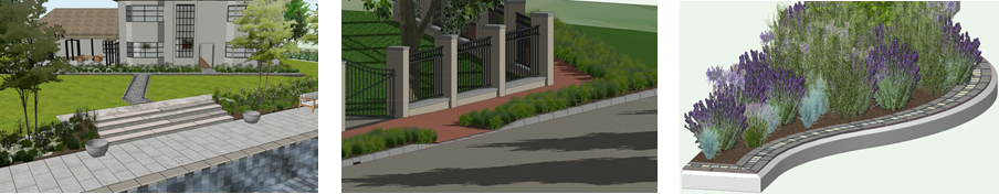
The Curb tool can be used to create a variety of objects including road curbs, hardscape borders, edging, and even coping stones around a swimming pool. They can be freestanding or associated with a hardscape or a landscape area. Curbs can be used to set elevations as site modifiers, and then related objects, such as hardscapes, can be aligned to the curb, or draped over the modified site model.
|
Mode |
Description |
|
Confirm
|
Executes the Associated Pick mode or Freestanding Pick mode operation |
|
Curb Style |
Opens the Resource Selector to select a curb style for placement; double-click a resource to activate it |
|
Associated Pick
|
Associates the curb with the edges of one or more selected hardscapes or landscape areas; see Placing curbs based on picked edges |
|
Freestanding Pick
|
Follows the edges of selected hardscapes, landscape areas, walls, or polylines to define the curb's path, without associating the curb with any of the selected objects; see Placing curbs based on picked edges |
|
Vertex
|
Draws a curb using the selected polyline creation options and current preference settings; see Drawing curbs manually |
|
Select All
|
For the Pick modes, selects all the edges of the selected objects. Select All and Select Individual modes can be used in combination. For example, to pick most but not all edges of an object, begin using Select All mode, and then use Select Individual mode to deselect the edges that are not needed. |
|
Select Individual
|
For the Pick modes, selects or deselects individual object edges by clicking them |
|
Polyline creation modes |
For Vertex mode, selects the method for drawing the polyline upon which the curb is based; see Creating polylines |
|
Preferences
|
Opens the Curb Preferences dialog box, to set default curb parameters; see Curb preferences |


General principles and guidelines for creating curbs
When you create a curb, the first decision to make is whether you need a curb or a border configuration.
The curb configuration, typically used along roadways, consists of either a single extrude or a series of symbols that are inserted according to radius rules (different symbols are used depending on each section's radius, but together, they create a single curb). The curb configuration can also be used to create edging (like pool copings), with radii settings to define the placement of fitted coping stones.
The border configuration covers most other situations, especially decorative ones. Borders can be made up of one or several rows; use the same symbol in each row, or a mix of symbols.
Curbs can be made up entirely of extrudes, entirely of 3D symbols, or of a combination of the two. Often a symbol is used for the visible portion of the curb, but the foundation, haunching and race are created with extrudes. The extrudes are essentially extrudes along path based on profile shapes; they can follow whatever shape the curb path takes.
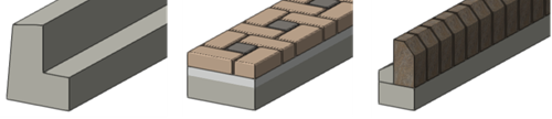
The curb style on the left is composed only of an extrude, and the two curb styles on the right are composed of extrudes to build the base and the bedding/haunching, and symbols for the top, visible portion
Using symbols as part of a curb allows for detailed reporting and quantity take offs for purchase. However, using curbs composed entirely of extrudes allows a more flexible, simpler workflow, when that level of detail isn't required.
Corners can be specified in the curb style; you can specify different corner symbols or cuts depending on the corner angle. When the curb is drawn, every corner setting can then be replaced or adjusted individually. Insertions such as dropped curbs can also be added to the curb, on a by instance basis. A curb can have as many different corners and insertions as needed.
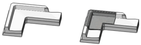
This curb with a gutter is made entirely of extrudes. On the left it has the default miter corner, and on the right, a corner symbol has been applied.
Insertion points for curbs are always at the top of the object and set to grade. This sinks the whole curb into the site model. To raise the main component over the surface, use the vertical offset setting. This gives you full control over how much of the curb should protrude above existing grade.
A curb can contain three site modifiers, a bottom, front edge, and rear edge modifier. You can't have edge modifiers without the bottom modifier. All modifiers are placed on the main component. The main component is by default the 3D symbol if specified, or the extrude intersecting the insertion point. This can, however, be changed; see Curb preferences: Path Extrudes pane. The modifiers follow the curb, but the edge modifiers' elevations can be edited. If a curb is associated with an object, only the outer edge will be editable. If the curb is placed inside the object's original boundary, the bottom modifier will be ignored; the curb will take on the modifier of the associated object. If it's placed outside the object, the bottom modifier will still be active.
When you draw a curb, the tool first creates individual objects between each corner vertex, and then automatically connects the pieces into a single curb. This avoids problems with extrusions at corners, but it also means that when you draw the curb path, you must place a vertex at every change of direction along a curve. Vertices like Bézier and Cubic are not suitable for the curb configuration.