Hardscape preferences
These settings are available in the following locations:
Hardscape Preferences dialog box (creating an object)
Hardscape Settings dialog box (editing an object)
Object Info palette (editing an object)
Edit Hardscape Style dialog box (creating or editing a style)
If a style is selected, only parameters set by instance can be edited (see Concept: Plug-in object styles). Instance parameters can be set independently for each instance of the object in the drawing.
Additional plug-in object settings for the 2D components and cut plane display are available; see Additional plug-in object style and instance options.
Hardscape preferences: Overall
Click to show/hide the parameters.Click to show/hide the parameters.
|
Parameter |
Description |
|
Hardscape Style |
Opens the Resource Selector to select a resource for placement |
|
Convert to Unstyled |
If Use Style is currently set to a style, select this option to convert the object to unstyled; the current values are retained, but all parameters are set to By Instance to allow editing |
|
By Style/Instance |
A graphic indicates whether each parameter is set to By Style and given a fixed value or set to By Instance and editable in the dialog box. An object style may have a combination of both settings, to balance the need for consistency and flexibility. By Style/Instance settings are established by the style and cannot be changed from the settings dialog box.
To edit the object style, see Editing plug-in object styles; editing the style modifies all plug-in objects in the file that use the style. |
|
Name Formula (Hardscape Style dialog box only) |
Enter the primary name of the hardscape style in the center field, and optionally select a prefix and/or suffix to autopopulate the style name based on the selected parameter values. For example a Name Formula of [Prefix=ID] [Main Name manually entered as "Flagstone Set on Sand"] [Suffix=Hardscape Category] might display as SE6 Flagstone Set on Sand Paving in the list of hardscape styles available for use. See Creating plug-in object styles for more general information about creating a plug-in object style. |
Hardscape preferences: General pane
Click to show/hide the parameters.Click to show/hide the parameters.
|
Parameter |
Description |
|
Class |
To control appearance and visibility, select a class from the list of classes present in the drawing, or create a new class; if this parameter is set by style, all instances using this style are assigned to this class. The current active class displays in the Hardscape Preferences dialog box. Changes here automatically update the class for the base fill in the Attributes palette, and also change the file's active class. |
|
Hardscape Category |
Optionally, select a hardscape category, or select Manage Custom Categories to edit the list. From the Manage Custom Categories dialog box, click Add or select a list item and click Edit, and then enter a new name. Select a list item and click Delete to remove it from the list of available categories. If a hardscape category is specified, it can be used in the instance or style name formula. |
|
Surface Layer |
Enter a name for the hardscape top layer, as you would refer to the style in design terms, not specifications. This can be used as part of the instance name formula; Vectorworks-provided hardscape styles use this name as the root of the style name |
|
ID |
Optionally, enter an ID for the hardscape. If an ID is specified, it can be used in the instance or style name formula. |
|
Instance Name |
Select whether to manually enter a name for this instance or to use a name formula. For Manual, enter a name For Instance name formula, select a name formula from the list of name formulas present in the drawing. Select Manage Custom Name Formulas to add, edit, or delete a name formula from the list; see below. |
Adding or editing an instance name formula
To create or edit a name formula for a hardscape instance:
On the General pane of the Hardscape Preferences or Hardscape Settings dialog box, select Instance name formula for the Instance Name.
In the list of name formulas, select Manage Custom Name Formulas to open the Manage Custom Instance Name Formulas dialog box.
Click Add, or select a name formula from the list and click Edit.
To delete a name formula from the list, select it and click Delete.
The Add/Edit Custom Instance Name Formula dialog box opens.
Click to show/hide the parameters.Click to show/hide the parameters.
|
Parameter |
Description |
|
Name |
Enter the formula's display name, for use in the list of name formulas |
|
Name Definition |
Displays the name formula, which can consist of selected name components and manually entered characters |
|
Name Component |
To add a name component to the name formula, select it from the list, and then click Add. The component is added to the end of the Name Definition. |
|
Integer/Lower-case character/Upper case character |
If Incrementing Value is selected for the Name Component, before clicking Add, select whether the value should be numeric, or a lower-case or upper-case letter. Enter the Start Value and Increment. For incrementing values to function, the Instance Name parameter must be set by style. |
Hardscape preferences: Specification pane
Click to show/hide the parameters.Click to show/hide the parameters.
|
Parameter |
Description |
|
Description |
Optionally, enter a description of the hardscape. The description can be long, such as a specification, or short. If short, this description can be used for the suffix in a hardscape style name formula. |
|
Permeability |
Includes permeability settings for the hardscape |
|
Permeable/Non-permeable |
Select whether the hardscape is permeable or non-permeable. If it is permeable, enter the Permeability Rate, and select the units. |
|
Runoff Coefficient |
Enter the runoff coefficient |
|
Sustainability |
Includes sustainability data for the hardscape |
|
Metric Framework |
The current metric framework, habitat type, and the habitat type's metric value display. To change these values, click Select Metric Framework; the available habitat type options change depending on the selected Metric Framework. |
|
Solar Reflectance Index (SRI) |
Enter the solar reflectance index value |
|
Unit Price |
Specifies a general unit price (for indicating the price per square unit in worksheets) |
|
Price Code |
Enter the price code (such as a SKU number) |
Hardscape preferences: Configuration pane
Click to show/hide the parameters.Click to show/hide the parameters.
|
Parameter |
Description |
|
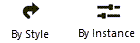
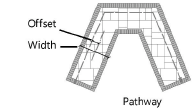
Boundary/Pathway |
Select which type of hardscape this is. Boundary defines the hardscape object with a user-defined polyline as the outer edge of the hardscape object (for example, to define regular or irregular patio areas).
Pathway defines the hardscape object with a user-defined polyline to create the linear path; for a pathway, enter the Width and Offset of the pathway centerline from the placement line.
When Hardscape Preferences is accessed from the Tool bar, this selection automatically switches the selected mode on the Tool bar to either Boundary Configuration mode or Pathway Configuration Center mode when the Preferences dialog box closes. To use a different pathway alignment mode, select the mode. |
|
Site Model Interaction |
Indicates whether and how the hardscape interacts with the site model. The selection made here changes the parameters available below. No Site Modifier: the hardscape does not modify the site model, and slab drainage functionality is not needed. Planar Pad: The hardscape is used as a planar pad site model modifier; see Creating a planar pad or pad with retaining edge. This kind of hardscape can interact with other site modifiers (depending on nesting, overlapping situations, and creation order). Slab Drainage (No Modifier): The main hardscape supports a drainage system, but the hardscape does not serve as a site modifier; see Creating slab drainage systems. The Slab Drainage tool can modify the main hardscape, adding slopes and ridges to the main slab geometry. If a border is specified, a border hardscape is created, but drainage elements are not applied to it. Aligned: The hardscape modifies the site model, and vertically matches the horizontal edges of certain geometry, including adjacent roadways, curbs, hardscapes, massing models, 3D polygons, landscape areas, walls, and planar pad or pad with retaining edge site modifiers. Aligned slabs are complex, non-planar hardscape types that can also be modified with vertical profiles, stake objects, and grade objects; see Creating an aligned site modifier. Path: This hardscape site modifier creates a surface defined by one longitudinal profile and a set of transverse profiles, with the path defined as a polyline; see Creating a pathway or boundary modifier. Texture Bed: Creates a texture bed out of the hardscape modifier, for use when the hardscape needs to display a specific image texture for a photorealistic rendered appearance, similar to the texture bed modifier; see Creating a texture bed. Draped: Conforms the hardscape to the site model surface rather than modifying it, though the hardscape components can still be cut into the site model. |
|
Existing/Proposed site model |
For a Texture Bed Site Model Interaction, select whether to display the texture bed on the existing site model or the proposed site model |
|
Cut into site model |
Allows the hardscape to cut into the site model to accommodate its components; if deselected, the hardscape is placed identically, but no excavation is done to the site model |
|
Elevation |
For planar pad or slab drainage, enter the elevation |
|
Start/End Elevation |
For a path, enter the elevations at the start and end of the path |
|
Slope Definition |
For a planar pad, select the method of defining the slope, or select None for a flat pad. After selecting the method, specify the Slope, and if needed, the Elevation at End of the slope, or the Contour Angle. |
|
Texture from Class |
Select <Hardscape Class> to use the texture specified for the hardscape class; select a class, or create a new class, to control texture bed appearance and visibility. The indicated class should have an overall texture applied on the Textures pane, with Use at Creation selected. See Concept: Applying textures by class. |
|
Drainage Settings |
For an existing slab drainage hardscape with drainage elements added, opens the Slab Drainage Settings dialog box. These settings are identical to those of a slab; see Slab drainage settings. |
|
Edit Components |
Opens the Hardscape Components dialog box for determining the structure that makes up the main area of the hardscape, as described in Creating hardscape components. The calculated Hardscape Thickness based on the components displays. |
Hardscape preferences: Border (legacy) pane
The recommended workflow is to use the Curb tool to create a border, instead of the settings on this pane; see Creating curbs.
Click to show/hide the parameters.Click to show/hide the parameters.
|
Parameter |
Description |
|
Add border |
Includes a border on the hardscape; when selected, border-specific attributes are available on the Attributes pane |
|
Components |
|
|
Width |
Enter the width of the border |
|
Border Components |
Opens the Hardscape Border Components dialog box, to specify the components for the hardscape border; see Creating hardscape components |
|
Border Unit Price |
Specifies a general unit price (for indicating the price per square unit in worksheets) |
|
Border Price Code |
Enter the price code (such as a SKU number) |
|
Graphics |
|
|
Pathway Borders |
Select the border configuration for pathway hardscape objects with borders
|
Hardscape preferences: Attributes pane
Click to show/hide the parameters.Click to show/hide the parameters.
|
Parameter |
Description |
|
Attributes list |
Lists all geometry that has graphic attributes settings. The class and graphic attributes of each part of the object are displayed. Components, if any, display for reference, but their attributes must be set in the Hardscape Component Settings dialog box; see Creating hardscape components. Select a line in the list browser and click Edit, or double-click a line, to set attributes for the part, and do any of the following: To control appearance and visibility, select a class from the list of classes present in the drawing, or create a new class. Select <Hardscape Class> to place the part in the same class as the hardscape object. Set the attributes; see The Attributes palette. You can also use the Attributes palette for existing unstyled hardscapes or for applicable "by instance" parameters. The border base fill and the first component are synced with the Base Fill and the Attributes palette, until a row is edited here, from the Attributes pane in the Hardscape Area Settings dialog box. Edits made here "break" the syncing. To specify a texture for a 3D part, select a texture from the Resource Selector, or click one of the buttons to use no texture, to use the class texture. Set the map type and rotation as needed; see Concept: Texture projection and orientation. For textures on a 3D part, select Follow longest edge to orient the texture along the longest edge of the part. This can prevent the texture from being flipped in a wrong direction. Material fills can only be set for hardscape components. |
|
Make All Attributes by Class |
Sets all fill, pen, line, and texture attributes by class; this option is not available from the preferences when the active class is set to Use at creation |
|
Remove All by Class Settings |
Removes all by class settings for fill, pen, line, and texture attributes; this option is not available from the preferences when the active class is set to Use at creation |
|
Joint Pattern Overlay |
Optionally, select an overlay for the main hardscape joint pattern; see Specifying hardscape joint patterns. When a resource such as a hatch style is selected, the Pattern name displays. The Stipple joint pattern overlays are processor-intensive for large hardscape objects and can significantly increase regeneration time. |
|
Joint Angle |
Sets the main hardscape joint angle |
|
Joint Class |
To control appearance and visibility, select a class for the joint pattern from the list of classes present in the drawing, or create a new class |
|
Border Joint Pattern Overlay/Angle/Class |
When Add Border is selected on the Border (legacy) pane, you can make specific selections for the border |
|
Border Joint Angle |
Sets the border joint angle |
|
Border Joint Class |
To control appearance and visibility, select a class for the border joint pattern from the list of classes present in the drawing, or create a new class |
|
Texture Settings |
Edits the textures of existing objects and styles; the settings cannot be edited from the Hardscape preferences |
Hardscape preferences: Tag (legacy) pane
Use of the Data Tag tool is recommended for labeling hardscapes; see Adding data tags and labels. However, these tag settings are available, if desired.
Click to show/hide the parameters.Click to show/hide the parameters.
|
Parameter |
Description |
|
Tag Display |
Select whether to display the hardscape tag to the right or left of the leader line, without a leader line (floating), or not at all |
|
Tag Style |
Select the ID tag display style. Name Only displays the name of the hardscape object only (as defined in the Name field). Name-Area(s) displays the hardscape object name, main area, and area of the border if applicable. Name-Area(s)-Perim displays the hardscape object name, main area, area of the border if applicable, and perimeter length. |
|
Tag Class |
To control appearance and visibility, select a class from the list of classes present in the drawing, or create a new class. Select <Hardscape Class> to place the tag in the same class as the hardscape object. |
|
Tag Approach Angle |
Specifies the angle of the leader line, from 0 to 360°. Setting the same angle for several selected hardscapes aligns their leader lines, for an attractive plan (see Aligning and distributing leader lines). |
|
Tag Shoulder Angle |
When a tag shoulder line is enabled, sets the angle of the shoulder line and, if selected, tag display, from 0 to 360°. To display the tag to the left, specify an angle greater than 90 or less than 270 degrees. To display the tag to the right, specify an angle less than 90 or greater than 270 degrees. Setting the same angle for several selected hardscapes aligns their shoulder lines, for an attractive plan. |
|
Tag Text Alignment |
Select whether the tag text is aligned on top of a continuation of the leader line, or centered vertically at the end of the leader line |
|
Snap tag to hardscape edge |
Select this option to automatically align the endpoint of the tag with the edge or corner of the hardscape that is nearest to the shoulder point of the tag |
|
Display tag line marker |
Displays a marker at the end of the leader line; specify the marker style by editing the hardscape tag class (see Setting class properties) |
Object Info palette
Hardscapes can be edited from the Object Info palette or by clicking Hardscape Settings from the Object Info palette. The fields in the Object Info palette are named similarly (but not always identically) to those in the Hardscape Preferences dialog box, and roughly reflect the order in which settings are entered in the dialog box, for ease of editing. For hardscapes using object styles, the parameters that are set by style display for informational purposes but cannot be edited.
Keep in mind the following when editing the hardscape properties:
To set individual border segments to invisible for boundary hardscapes or cut-out holes, select the hardscape object, and then click the Reshape tool. Click Hide or Show Edges mode. Click the midpoint of the hardscape border segments or the cut-out hole to hide. Repeat this process to set the border segments back to visible, if necessary.
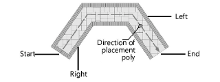
To quickly determine the left and right side of a pathway hardscape object, select the hardscape object and click the middle button next to the Vertex field on the Shape tab of the Object Info palette; when the button is clicked, the first vertex of the hardscape object is highlighted with a red box.
When classing the subparts of the hardscape object, such as for the joints or tags, the class visibility of the specified class controls the visibility of the corresponding subcomponent. The class attributes are only applied to the corresponding subcomponent when the Use at Creation option is selected for the class. For example, if the Joint Class is set to the Hardscape - Component - Main Joint class, and that class specifies a hatch Fill Style, edit the class and select the Use at Creation option to apply the fill attribute. See Setting class attributes.
Parameters that are available in a dialog box are described in the tables above. Only the parameters that are different are described here.
Click to show/hide the parameters.Click to show/hide the parameters.
|
Parameter |
Description |
|
Replace, remove, or edit the current style, or create a new plug-in object style for this object; see Changing plug-in object styles from the Object Info palette. Editing a style changes all instances in the file that use the style. |
|
|
Hide style parameters |
Hides the parameters that are set by style; these cannot be edited from the dialog box or Object Info palette |
|
Main Area Graphics |
|
|
Joint Pattern Size X/Y |
Specifies the size of the joint pattern units, for flagstone, pavers-grid, and pavers-running joint patterns |
|
Joint Pattern Angle |
Specifies the rotation angle of the joint pattern |
|
Site Modifier |
|
|
Site Modifier Interaction |
The selection made here changes the parameters available |
|
Simplification Tolerance |
Enter a positive value to redefine the horizontal distance between the closest parts of two neighboring portions of the modifier. A longer distance simplifies the modifier polygon, reducing the number of source points that modify the site model. A shorter distance increases the number of source points that modify the site model. A value of 0 (zero) does not simplify the modifier. |
|
Modifier Vertex Count |
Displays the number of vertices created by the hardscape to modify the site model |
|
Update Site Model |
Updates the site model with any site model modifications that have occurred. If the update causes the site model contours to fall outside the minimum/maximum elevation range specified in the site model settings, an alert displays, allowing the range to be adjusted. |
|
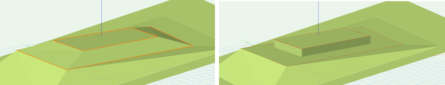
Vertical sides for inner modifiers |
Determines whether inner modifiers, such as a hardscape within grade limits, create a transitional surface (when disabled) or a vertical retaining edge (when enabled)
Vertical sides for inner modifiers deselected (on the left) and selected (on the right) |
|
Pad (Planar Pad) |
Defines the hardscape with a 3D polygon that represents a shape to modify the site model |
|
Elevation (Planar Pad) |
Sets the elevation of the pad at its reference elevation control point |
|
(Planar Pad) |
Defines the slope of the hardscape and its start and end points. Click to place the start end of the slope, at the elevation of the hardscape, and click again to set the direction of the slope and place the end point. The Slope Definition dialog box opens to set the slope parameters. For more information on creating a sloping planar pad, see Creating a planar pad or pad with retaining edge. |
|
Aligned (Aligned) |
Uses the hardscape as a non-planar slab that automatically matches relative elevations along horizontally collinear edges of adjacent roadways, hardscapes, massing models, extrudes, 3D polygons, landscape areas, walls, and pad/pad with retaining edge site modifiers |
|
Realign |
Resets the surface alignment with surrounding geometry |
|
Selects the objects to align to, based on the layer location of the objects. This offers flexible control over the alignment. All Layers: Aligns the hardscape with geometry from any layer in the file Visible Layers only: Aligns the hardscape with modifiers from visible layers only; geometry on invisible layers does not affect the hardscape Same Layer as Modifier: Aligns the hardscape with geometry that exists only on the same layer Select Layers: Opens the Select Layers dialog box, to choose which layers with geometry can affect the hardscapt alignment. Click in the Use column to select a layer. To create a new design layer, click New Layer; specify the name for the new layer, and click OK. Custom Set of Layers: Opens the Select Layers dialog box, to select or to modify the selected layers |
|
|
Interpolate surface |
Increases the level of detail of the surface created by the profiles and modifiers |
|
Smoothness Sampling |
Enter the sampling rate (0 – 100); higher values add vertices and increase the smoothness |
|
Falloff |
Enter the percentage (0 – 100). This value determines the effect of the surface's defining elements (profiles, stakes, grade objects and adjacent objects) on the interpolated surface. The bigger the value, the less the influence of the defining elements. When the Interpolation Type is Concave, falloff values control the curvature of the surface. Larger falloff values result in a straighter, less curved surface; lower falloff values create a varied curved surface with hills and valleys. When the Interpolation Type is Convex, larger falloff values "pull" more on the surface points. The surface points may move close to the minimum elevation. |
|
Interpolation Type |
Select Concave or Convex, depending on the surface, the falloff value, and the desired results. Concave uses multiquadratic radial function calculations, and usually produces the best results. The surface effects are more stable and minimize the curvature. Convex uses inverse multiquadratic radial function calculations, and is useful when a bigger falloff is desired. The gravitational effect of this option pulls the surface points down to the minimum elevation based on their distance from the defining elements (profiles, stakes, grade objects and adjacent objects). |
|
Elevation |
Specifies the modifier elevation (does not apply to the aligned edges) |
|
Profiles (Aligned) |
Modifies the surface of the hardscape with profile lines; see Editing aligned hardscapes or modifiers with profile lines |
|
Profile |
Scrolls through the profiles, highlighting the selected one; click the center button to highlight the current profile |
|
Name |
Displays the name of the currently selected profile |
|
Profile Line Class |
Select <Hardscape Class> to place the profile in the same class as the hardscape; select a class, or create a new class, to control profile line appearance and visibility. |
|
Show profile lines |
Toggles the display of all profile line parameters (name, slope, elevation, and markers) |
|
Show profile names |
Toggles the display of all profile names |
|
Show slopes |
Toggles the display of all slope values |
|
Show vertex elevation |
Toggles the display of all vertex elevations |
|
Show profile line markers |
Toggles the display of all profile markers |
|
Add Profile |
Adds a profile line to the hardscape for modifying the surface |
|
Edit Profile |
Enters editing mode for the selected profile, for Editing aligned hardscapes or modifiers with profile lines |
|
Reverse Direction |
Reverses the direction of the profile line section |
|
Profile Line Marker Styles |
Opens the Set Marker Style dialog box, to select the profile marker type at each end of the profile line; markers can be the same (Match Beginning) or different (Differentiate) at each end of the section line |
|
Delete Profile |
Deletes the selected profile |
|
Surface Modifiers (Aligned) |
Modifies the surface of the hardscape with stake and grade objects |
|
Show stake objects |
After modifying the hardscape with stake objects, displays the stake objects |
|
Show grade objects |
After modifying the hardscape with grade objects, displays the grade objects |
|
Edit Surface Modifiers |
Edits the surface modifiers; see Editing aligned hardscapes or modifiers with surface modifiers |
|
Longitudinal Profile (Path) |
|
|
Edit Profile |
Enters editing mode for the selected profile, for Editing aligned hardscapes or modifiers with profile lines |
|
Start Elevation/End Elevation |
Enter the starting and ending elevation of the modifier; alternatively, enter one of the elevations and ender a Slope value to automatically calculate the other elevation |
|
Slope |
Enter the slope value; alternatively, when the Start Elevation and End Elevation are entered, the slope displays |
|
Realign Elevations |
If changes occurred to an elevation, resets the affected vertex elevations |
|
Fit to Surface |
Conforms the longitudinal profile line to the surface of the site model |
|
Profile Line Class/Profile Text Class |
Select <Hardscape Class> to place the profile or its label text in the same class as the hardscape; select a class, or create a new class, to control profile line appearance and visibility |
|
Elevation Marker |
Select the elevation indicator type |
|
Elevation Marker Factor |
Specifies the scale factor of the elevation marker |
|
Slopes Grade Def |
Determines the how the Slope is calculated and displayed |
|
Show profile line |
Shows profile lines when profiles are added to edit the aligned slab (see Editing aligned hardscapes or modifiers with profile lines) |
|
Show slopes |
Toggles the display of all slope values |
|
Arrow indicates downward |
When Show slopes is selected, adds an arrow to indicate which side slopes down |
|
Show vertex elevation |
Toggles the display of all vertex elevations |
|
Show profile line markers |
Toggles the display of markers at the ends of the profile line |
|
Profile Line Marker Styles |
Opens the Set Marker Styles dialog box, to select the profile marker type at each end of the profile line; markers can be the same (Match Beginning) or different (Differentiate) at each end of the section line |
|
Transverse Profiles |
|
|
Profile |
Scrolls through the profiles, highlighting the selected one; click the center button to highlight the current profile |
|
Name |
Displays the name of the currently selected profile |
|
Profile Line Class Profile Text Class |
Select <Hardscape Class> to place the profile in the same class as the hardscape; select a class, or create a new class, to control profile line appearance and visibility |
|
Slopes Grade Def |
Determines the how the Slope is calculated and displayed |
|
Show profile lines |
Toggles the display of all profile line parameters (name, slope, elevation, and markers) |
|
Show profile names |
Toggles the display of all profile names |
|
Show slopes |
Toggles the display of all slope values |
|
Arrow indicates downward |
When Show slopes is selected, adds an arrow to indicate which side slopes down |
|
Show vertex elevation |
Toggles the display of all vertex elevations |
|
Show profile line markers |
Toggles the display of markers at the ends of the profile line |
|
Add Profile |
Adds a profile line for modifying the surface |
|
Edit Profile |
Enters editing mode for the selected profile, for Editing aligned hardscapes or modifiers with profile lines |
|
Profile Line Marker Styles |
Opens the Set Marker Style dialog box, to select the profile marker type at each end of the profile line; markers can be the same (Match Beginning) or different (Differentiate) at each end of the section line |
|
Delete Profile |
Deletes the selected profile |
|
Border |
|
|
Border Pattern Size |
Sets the width of the spaced joints, when spaced joints are selected for the border |
|
Border Pattern Angle |
Enter the angle of the pattern inside the border |
|
Information |
|
|
Main Area |
Displays the size of the main area |
|
Border Area |
Displays the size of the border area |
|
Footprint Area |
Displays the area of the entire footprint of the hardscape |
|
Main Perimeter |
Displays the perimeter measurement of the main area polyline |
|
Border Perimeter |
Displays the perimeter of the border only |
|
Footprint Perimeter |
Displays the perimeter measurement of the entire footprint polyline |
|
Site Modifier Information |
|
|
Update Calculations |
Updates the area and volume calculations displayed in the Object Info palette for the area of the site model located under the hardscape modifier (grade limits must exist around the pad) |
|
Site model area and volume data |
Displays the area and volume information for the site model area located under the site modifier; select the units for the area and volume (grade limits must exist around the pad). For more information, see Site model properties. |