Editing objects in a door and window assembly
|
Tool |
Tool set |
|
Edit Assembly
|
Assembly Edit |

In an assembly layout's object editing mode, the Edit Assembly tool edits assembly frames and mullions, door and window units, and accessories such as lintels, sills, and trim that have been added to an assembly. Within an assembly layout, the individual objects may also use a style, and the by style/by instance settings of each object determine what can be edited within the layout. Object size constraints, such as adding a unit with a fixed size between mullions that may or may not have fixed spacing, may affect editing behavior; adjust objects and settings as needed.
|
Mode |
Description |
|
Edit Frames and Mullions
|
Activates the modes (described below) to reshape assembly frame segments and mullions and to add, split, and combine mullions |
|
Edit Unit
|
Edits selected window, door, panel, symbol, and wall infill units in the assembly |
|
Edit Accessory
|
Edits selected accessories in the assembly |
|
Edit Frames and Mullions (Edit Frames and Mullions primary mode only)
|
Repositions, deletes, and changes the settings of selected frame segments and mullions |
|
Add Mullion (Edit Frames and Mullions primary mode only)
|
Inserts new mullions into the assembly |
|
Split Mullion (Edit Frames and Mullions primary mode only)
|
Splits a mullion into multiple pieces, so that each portion of the mullion can be independently moved, edited, or deleted. To split a mullion where two continuous mullions intersect, position the split cursor so the long center line is parallel with the mullion to split, and click. |
|
Combine Mullions (Edit Frames and Mullions primary mode only)
|
Combines two collinear mullions into a single mullion |
|
Mullion Style (Add Mullion submode only) |
Opens the Resource Selector to select a resource for placement; double-click a resource to activate it. |
|
Preferences (Add Mullion submode only)
|
Opens the Mullion Preferences dialog box to set default parameters; see Door and window assembly settings: Default Mullions pane |


Edit Frames and Mullions mode
Select a frame segment or mullion to edit its settings in the Object Info palette. For frames, only the class and width can be changed; the angle of the frame segment's position in the drawing area displays. For the mullion settings, see Door and window assembly settings: Default Mullions pane. Interactively edit the objects in the drawing, depending on the selected submode, as described below.
Edit Frames and Mullions mode: Use the handles and/or the floating Data bar to change the position and size of the selected object, or press Delete on the keyboard to remove it. Units adjacent to frame segments and mullions move when the frames and mullions move, as long as the objects' constraint rules allow it.
Add Mullion mode: Select a mullion style or click Preferences on the Tool bar to set the default preferences, and then add a mullion by drawing a line from one frame or mullion to another.
Split Mullion mode: Position the cursor with the long line parallel to the mullion to split, and then click to split it where it intersects with another frame or mullion.
Combine Mullions mode: Click two collinear mullions to combine them into one.
When Edit Frames and Mullions mode is active, two context menu commands are available to help distribute frame segments and mullions. When three or more parallel frame segments and/or mullions are selected, right-click on a selected part, and select one of the following commands from the context menu:
Distribute Spacing distributes the selected parts to have an equal amount of space between each (from edge to edge).
Distribute Centerlines distributes the selected parts to place equal distance between their centerlines, regardless of their width.
Edit Unit mode
Select a window, door, panel, symbol, or wall infill unit in the assembly, and use the handles to interactively reshape the unit (this may also reshape or resize an entire section of the assembly, depending on the unit's location).
Some unit types have shape restrictions. For example, doors, wall infills, and symbols must be rectangular; if you edit the layout so that a unit's shape is made non-rectangular, the unit is automatically replaced with a panel of the assembly's default panel style (selected on the General pane; see Door and window assembly settings: General pane). You can change the panel in the layout's object editing mode. Panels can fit themselves to any shape between the frames and mullions, as can windows, though a window's configuration options are limited when it's non-rectangular.
The unit's settings can be edited in the Object Info palette. All unit objects have an Assembly Constraints section at the top of the Object Info palette that is available only within the layout's object editing mode. These options, which don't restrict modifications in object editing mode, allow you to set unit size constraints and repetition behaviors that control how individual units respond when the overall assembly is reshaped or resized on a design layer.
Setting the unit's height and width by style is another way to ensure those measurements remain unchanged when the assembly is reshaped.
Click to show/hide the parameters.Click to show/hide the parameters.
|
Parameter |
Description |
|
Fix width |
Locks the width of the unit to what is set in the layout's object editing mode, if the assembly is resized on a design layer. The unit can always be resized as needed in object mode. This can be especially useful to maintain a door size if the overall assembly is being made wider. |
|
Fix height |
Locks the height of the unit to what is set in the layout's object editing mode, if the assembly is resized on a design layer. The unit can always be resized as needed in object editing mode. This can be especially useful to maintain a door size if the overall assembly is being made taller. |
|
Unit Object Type |
To change the type of unit from/to a window, door, panel, symbol, or wall infill, select the new option. Doors must be a rectangular shape, so changing the unit shape automatically converts a door to a panel. Symbols are placed based on their insertion point rather than face alignment, so if you change another unit type to a symbol, check for proper alignment relative to the frame, mullions, and other units. |
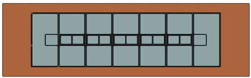
The door's width is fixed, so the windows widen when the assembly is resized, but the door doesn't
The remaining settings are specific to the unit's object type or (for parameters including Unit Offset Reference and so on) to the door and window assembly object settings. Edit them directly in the Object Info palette or click Settings to open the [Object] Settings dialog box; some parameters are restricted or unavailable for assembly units.
Door and window assembly settings
Edit Accessory mode
Select a lintel, sill, stool, trim, or shutter in the layout, and edit its settings in the Object Info palette. See Adding accessories to a door and window assembly for information about accessory object parameters.