Editing
the Hardscape Object Settings
Editing
the Hardscape Object Settings
Editing
the Hardscape Object SettingsThe parameters can be edited for selected hardscape objects through the Hardscape Settings button on the Shape tab of the Object Info palette. To modify the default hardscape object settings, click the Preferences button on the Tool bar.
Many of the parameters are identical to those used to create the hardscape object (see Creating Hardscape Objects). However, certain parameters are accessible from the Object Info palette only.
If the hardscape is sloping, specify the slope properties in the Object Info palette and/or by adjusting slope indicator control points and reshaping the hardscape corners.
● Select the method of defining the slope from the Slope Def list in the Object Info palette, and specify the slope parameters. The slope parameters do not display for a Slope Def of None. As values are entered in the Object Info palette, the other parameters are automatically calculated and displayed.
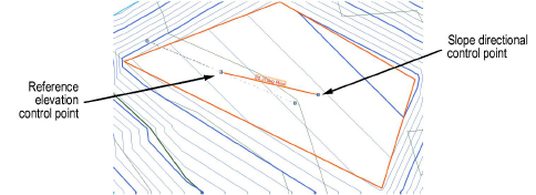
● A banked slope can be contoured. The reference elevation control point indicates the start elevation of the hardscape, and the dashed line that passes through the reference elevation control point represents a constant elevation along the line. The dashed line indicates and controls the Contour Angle in the Object Info palette; it is only visible when the hardscape is selected with the Selection tool, and it does not print. All the points on the line are at the same elevation; move the contour angle control points to define how the hardscape is banked along the hardscape slope. The contour angle must always be between 1 and 90 degrees of the slope vector (the banked contour cannot be parallel or perpendicular to the hardscape slope).
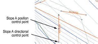
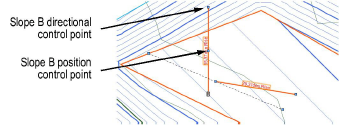
● In addition to the hardscape slope, up to two custom slope axes can be specified: Slope A and Slope B. Slope arrows can be displayed on the hardscape to indicate the slope angles of the main slope and the two custom axes; select Show Slope, Show Slope A, and/or Show Slope B. The slope arrows are interactive; move a control point to adjust the slope direction, and the slope at that location is displayed. The control points of the slope arrows are only visible when the hardscape is selected with the Selection tool, and they do not print.
● The Object Info palette displays the Elevation at End so that hardscapes that meet at the bottom of a slope can be set to the same ending elevation. The planes for two hardscapes match when their contour lines are parallel, and the starting point of one hardscape is on the plane of the other hardscape.
● In 2D view, select the control points of the slope arrows or the contour angle indicator, to interactively display the slope at that location. Changes to the slope values in the Object Info palette affect all the slope parameters. To set the slope plane, change the slope and the contour angle, or change slope A and slope B.
● In 2D view, the Reshape tool changes the shape of the hardscape.
► Click to show/hide the parameters.
To set individual border segments to invisible for boundary hardscapes or cut-out holes, select the hardscape object, and then click the Reshape tool. Click Hide or Show Edges mode. Click the midpoint of the hardscape border segments or the cut-out hole to hide. Repeat this process to set the border segments back to visible, if necessary.
To quickly determine the left and right side of a pathway hardscape object, select the hardscape object and click the middle button next to the Vertex field on the Shape tab of the Object Info palette; while the button is clicked, the first vertex of the hardscape object is highlighted with a red box.
When classing the subcomponents of the hardscape object, such as for the joints or tags, the class visibility of the specified class controls the visibility of the corresponding subcomponent. The class attributes are only applied to the corresponding subcomponent when the Use at Creation option is selected for the class. For example, if the Joint Class is set to the Hardscape - Component - Main Joint class, and that class specifies a hatch Fill Style, edit the class and select the Use at Creation option to apply the fill attribute. See Setting Class Attributes.
A hardscape object can be used as the basis of a retaining wall. This provides the ability to sculpt the site model around the hardscape. See Creating Retaining Walls.
Double-click the hardscape object to activate the Reshape tool, or select the Reshape tool from the Basic palette. Select the object handles to reshape the hardscape object. For more information, see Reshaping Objects.
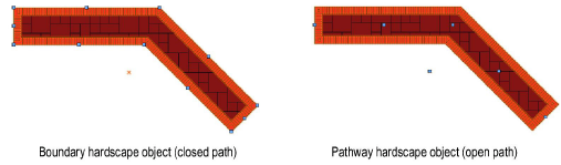
After creation, a boundary hardscape object can be converted to a pathway hardscape object, and similarly, a pathway configuration can be converted to a boundary configuration. The conversion preserves the appearance, but the path of the object changes.
To convert a boundary hardscape object to a pathway hardscape configuration:
Select the boundary hardscape object.
Right-click on the hardscape object and select Convert to Pathway from the context menu.
To convert a pathway hardscape object to a boundary hardscape configuration:
Select the pathway hardscape object.
Right-click on the hardscape object and select Convert to Boundary from the context menu.
Alternatively, click Hardscape Settings from the Object Info palette of a selected hardscape object, and select the configuration.
Hardscape tags can be adjusted in several ways.
● When hardscape tags are required, their default appearance is normally specified in the hardscape object settings.
● Individual hardscape tags can then be changed for selected hardscape objects by adjusting the hardscape tag parameters from the Object Info palette.
● The hardscape tag class controls the appearance of the leader/shoulder lines, as well as the marker style.
● To align hardscape tags for improved readability, use the Align/Distribute Leader Lines command (see Aligning and Distributing Leader Lines).
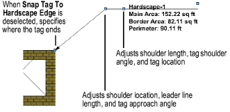
● If an individual tag needs to be repositioned, hardscape tags also have two control points for adjusting the shoulder length, tag shoulder angle, and tag location; or the shoulder location, leader line length, and tag approach angle.
Once the hardscape object is set to the desired appearance, you can save the settings for future use or for import into other files.
To save the selected hardscape object settings:
Select a hardscape object.
From the Object Info palette, click Save Hardscape.
The Name Hardscape Symbol dialog box opens.
Enter a unique name.
Click OK.
The hardscape settings are saved as a resource in the “Hardscapes” symbol folder in the active file. Boundary and pathway hardscape objects are assigned unique thumbnail view icons for easy identification. See Resource Manager.
To use a saved hardscape object, do one of the following:
● To draw a hardscape with the Hardscape tool, click Hardscape on the Tool bar. From the Resource Selector, double-click a resource to activate it.
● To apply saved settings to an existing hardscape, from the Resource Manager, right-click on the resource, and select Apply from the context menu. Alternatively, double-click on the resource or drag the resource onto an object to apply it.
~~~~~~~~~~~~~~~~~~~~~~~~~