 Drawing a stair with Corner Vertex mode
|
Mode |
Tool |
Workspace: Tool set |
|
Corner Vertex
|
Stair
|
Architect and Landmark: Building Shell Spotlight: Customize workspace to add tool (see Customizing workspaces) |


Corner Vertex mode draws a stair based on a polyline with up to six vertices. The standard configuration/resource selected for the stair must match the number of vertices in the polyline. Some stair configurations require 90° angles. Snap to adjacent building elements to precisely place the outer boundary of the stair. If there are certain stair geometry parameters you want to set for the stairs, specify them in the Stair Settings dialog box first. The stair's overall dimension settings (Stair Width, Side, Length, and so on) adjust to match the stair's drawn outer boundary, and as many as possible of the other stair geometry settings remain unchanged in stair settings when the Stair tool calculates the stair.
Geometry settings such as Tread Depth, Number of Risers, and Offset are not defined by the shape, but they may require adjustment to create a valid stair.
If the stair will have a lower layer and upper layer representation, or if its total rise will be defined by layer or story elements, it should be inserted on the layer representing the lower of the two floors it connects.
To draw a stair:
From the appropriate layer, click the tool and mode.
Click Left Control Line mode or Right Control Line mode to draw the stair on the left or right side of the polyline.
Optionally, to manually set the stair's total rise value after placement in a 3D view, click Height of Stair mode; see Manually setting the total rise of a stair. Deselect the mode to use the total rise value from the stair settings, or to set the total rise by layer elevation.
Do one of the following:
Click Stair on the Tool bar to select a resource from the Resource Selector.
Click Preferences to open the Stair Settings dialog box and specify the tool’s default parameters; see Stair settings.
The parameters can be edited later from the Object Info palette.
Click to set the polyline's start point.
Click to set the end of the segment and the beginning of the next. The shape and location of the stair previews; an arrow indicates the direction of the stair.
Continue drawing segments; double-click to complete the polyline.
The Stair tool calculates the stair based on the polyline and the current stair settings, including the configuration and other geometry settings, such as the Tread Depth and Riser Height. If a valid stair is calculated, the stair is created. If not, either the stair fails, or you are given options to change the invalid settings.
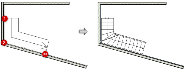
In this example, the polyline used to create an L-shaped stair must have exactly three vertices; this stair configuration does not require 90° angles
Consider whether to save the stair as a symbol; see Saving a stair as a symbol.
If the same customized stair is to be used numerous times in a drawing, or will be used in another drawing or by another designer, this eliminates the need to repeatedly apply parameters, maximizes memory efficiency, and allows global editing of symbols. See Concept: Vectorworks symbols.
If you don’t wish to create a symbol, the stair attributes can easily be transferred.
Requirements for stairs drawn with Corner Vertex mode
There are certain mathematical/geometric conditions for drawn stairs. The Stair tool may fail to create a stair that violates these conditions, or that may result in an unexpected shape or placement.
The standard configuration selected for the current stair must have the same number of vertices as the polyline drawn with Corner Vertex mode. For example, a straight stair must have two vertices, and a U-shaped stair must have four vertices. If this condition is not met, the Select a Stair Configuration dialog box opens, so you can select a configuration that matches the polyline. Only configurations that are compatible with the polyline are available.
Some stair configurations require 90° angles.
Some stair configurations support angles other than 90°, but many do not; this is indicated on the Select a Stair Configuration dialog box. The stair configurations that require a 90° angle have a 0.25° tolerance for hand-drawn shapes.
There are some potential stair shapes, such as Z-shaped stairs, or stairs with 5 or 6 vertices and non-90° angles, for which the Stair tool has no standard configuration. Stairs with these shapes cannot be created.
