Quick Start: Let's create the schematics and layout for a school performance
Difficulty level: Beginner
ConnectCAD lets you model the equipment, connections, and cabling required for electronic networks. In this tutorial, you'll create an audio network for a school band playing in an auditorium. You'll learn how easy it is to:
Create a new drawing and add devices
Connect the devices
Create a layout to show the position of equipment within a rack, at scale
Create a report that lists the parts in the drawing
The location of commands and tools varies, depending on the workspace. You can learn to use the Quick Search feature to quickly find commands or tools; see Quick Search. You can also look at the Commands and tools PDF here in the Vectorworks help system.
Add a device to a new drawing
To start, let's create a new drawing, add a device to the drawing, and then customize the device.
Select File > New, and then select a ConnectCAD template, either imperial or metric.
A new drawing opens in Top/Plan (2D) view.
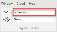
Select the Schematic design layer from the View bar or the Navigation palette.
Click the Device tool ![]() and draw a device approximately 2 inches wide by 3 inches high (50 mm by 76 mm).
and draw a device approximately 2 inches wide by 3 inches high (50 mm by 76 mm).
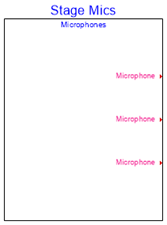
In the Object Info palette, change the Device Name and Display Tag to Stage Mics and the Description to Microphones.
The device name/display tag and description display on the device.
Click the Socket tool ![]() . On the Tool bar:
. On the Tool bar:
Specify Microphone as the Name.
Click the Output and Right Socket modes.
Select the MIC/LINE (mic or line analog audio) Signal type. (The connector is automatically selected for you.)

Click to place three microphones on the device, one for each student on stage. The microphones are output only, so they go on the right side of the device.
Add a mixer
The microphones are wired to a mixer in the control room at the back of the auditorium. Let's add the mixer to the schematic.
Click the Device Builder tool ![]() and then click in the drawing to the right of the microphones.
and then click in the drawing to the right of the microphones.
The Device Builder dialog box opens.
Select a manufacturer's mixer:
Category: Audio > Mixer-Small
Make / Model: Yamaha / EMX312SC
Device Name and Display Tag: Yamaha Mixer. (If desired, you can change the Display Tag.)
Height (Rack Units): 2
The Preview pane displays a preview of the mixer.
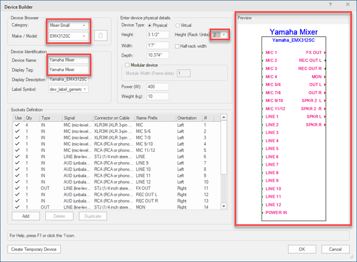
Click OK to add the mixer to the drawing.
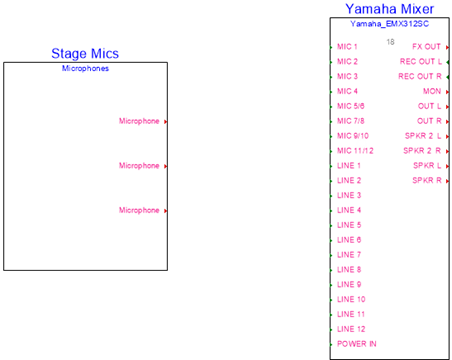
Add speakers
The mixer sends sound out to four speakers in the auditorium. Let's add the speakers to the schematic.
Click the Device Builder tool again, and then click in the drawing to the right of the mixer to open the Device Builder dialog box.
Select a manufacturer's speaker:
Category: Audio > Speaker
Make / Model: JBL / EON206P
Device Name and Display Tag: Speaker
Because the speaker is not placed in a rack frame, you don't have to specify the Height (Rack Units).
Click OK to add the speaker to the drawing.
With the speaker selected, select Edit > Duplicate Array.
The Duplicate Array dialog box opens.
Set the following attributes:
Shape: Linear Array
Number of Duplicates: 3
First Duplicate's Position Determined By: Next Mouse Click
Click OK, and then click below the first speaker to add three duplicate speakers.
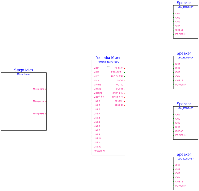
Optionally, you may want to line up the speakers vertically with the Align/Distribute command. Align the selected speakers to the Left edge.
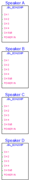
Label the speakers
To label the speakers:
Click the Selection tool  , and select all four speakers.
Select ConnectCAD > Drawing > Renumber ConnectCAD Objects.
The Labeling Options dialog box opens.
Select the Alpha option. You can keep most of the default values, but let's change the Delimiter to <space>. Then select a Numbering Direction. The Example group box shows how the devices will be labeled.
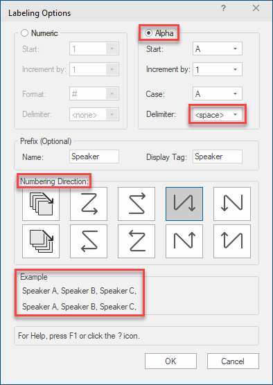
Click OK to label the speakers A, B, C, and D.
Add a CD/media player
Let's use the Device Builder tool one more time to add a CD/media player. The band wants to play an audio file in the background.
Click the Device Builder tool, and then click in the drawing below the Stage Mics device to open the Device Builder dialog box.
Select a manufacturer's CD/media player:
Category: Audio > CD/Media Player
Make / Model: Denon > DN-300Z
Device Name and Display Tag: Media player
Height (Rack Units): 1
Click OK to add the media player.
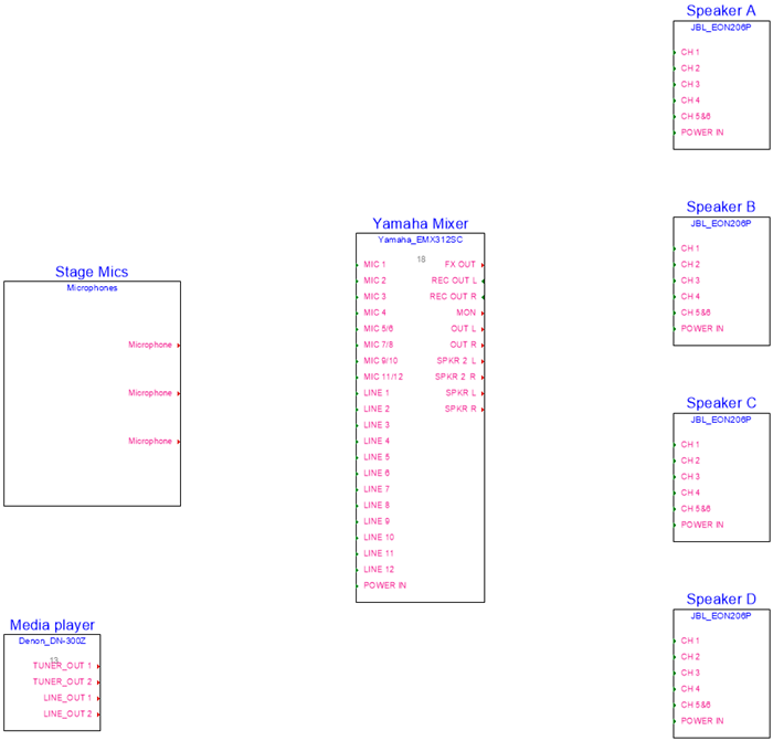
Connect the devices
Now we need to connect the devices that were added to the drawing.
Click the Connect tool ![]() .
.
Connect the microphones to the mixer by clicking each Microphone socket and connecting it to a MIC socket on the mixer. A circuit is created.
Optionally, select Multi Connect mode ![]() to connect multiple microphone sockets to multiple mixer sockets at one time.
to connect multiple microphone sockets to multiple mixer sockets at one time.
You can click on two sockets to connect them, or, after clicking on the first socket, you can click on different places in the drawing to set intermediate points for the circuit path.
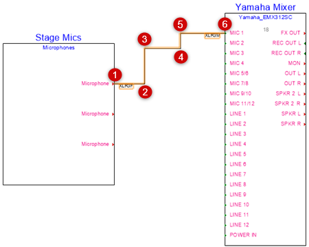
You can also use the Reshape tool  with Add Vertex mode
  to add vertices to the circuit, and then drag a handle to reshape the circuit path.
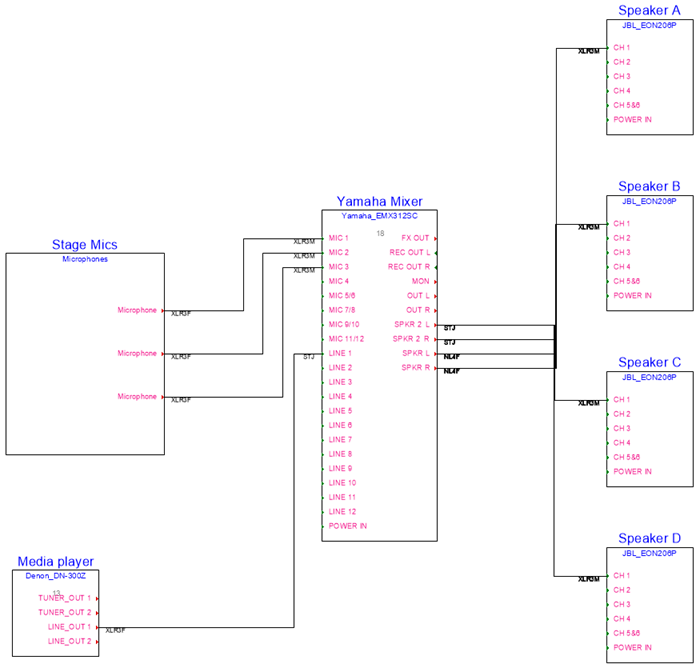
Connect the LINE_OUT 1 socket on the media player to the LINE 1 socket on the mixer.
Connect each of the mixer speaker outlets (SPKR 2 L, SPKR 2 R, SPKR L, SPKR R) to CH 1 on each speaker. For each circuit, from the Object Info palette, select "ADAT (unbalanced 8 channel digital audio)" for the Signal type.
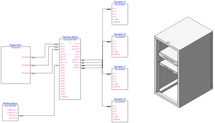
We now have our schematic.
Create a layout
Vectorworks can create 3D equipment items from the schematic devices in the drawing. Let's create a simple layout view of the schematic.
Select the mixer and media player devices.
Switch to the 3D Layout design layer.
Select ConnectCAD > Layout > Create Equipment.
The Create Equipment dialog box opens.
Click Deselect All Layers, and then click in the Use column next to the Schematic layer.
Select Selected devices only.

When you click OK, 3D equipment for the media player and the mixer are placed in the drawing. Let's put them into an equipment rack.
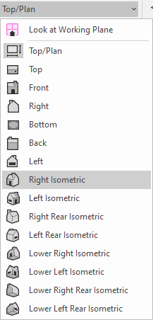
On the View bar, select Right Isometric from the Current View/Standard Views list, or just press 3 on your numeric keypad or use the Onscreen View Control cube to switch to a 3D view.
Click the Equipment Rack 3D tool ![]() and then click twice in the drawing to place a rack. With the rack selected, select a Height of 25 (since this is a small equipment rack) in the Object Info palette.
and then click twice in the drawing to place a rack. With the rack selected, select a Height of 25 (since this is a small equipment rack) in the Object Info palette.
Using the Selection tool , Drag the equipment into the rack, or drag to reposition the equipment.
Now if we model the control room at the back of the auditorium, we have our 3D models, and they are connected to the schematics on the Schematic design layer.
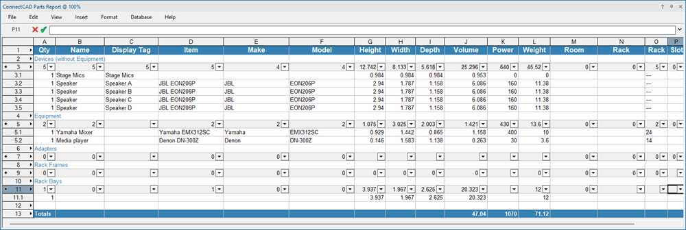
Create a report
Let's create a report for the theater manager that lists the parts that we plan to use. Let's do this in a Vectorworks worksheet.
Select ConnectCAD > Documentation > ConnectCAD Parts Report.
The worksheet is created and opens automatically. The devices and their locations are nicely laid out for anyone who needs the information.