Quick Start: Let's render a simple scene
Difficulty level: Beginner
Rendering gives a solid appearance to 3D objects, and can be used to show textures, lighting and shadows, and other visual effects. It can be a complex process to produce photo-realistic or highly stylized drawings, but a few simple steps can let you produce a basic rendering that gives an idea what your design may look like when it's built. In this topic, you'll apply texture to different kinds of 3D objects, light a scene, set the view you want, and select a rendering mode, to showcase your work.
The location of commands and tools varies, depending on the workspace. You can learn to use the Quick Search feature to quickly find commands or tools; see Quick Search. You can also look at the Commands and tools PDF here in the Vectorworks help system.
Add and apply texture to 3D objects
There are different ways to apply textures to different kinds of 3D objects. Let's add a few objects of different types to get a feel for how this works.
Some of the 3D objects described below require a license for a Design Suite product, as indicated, but texturing and rendering in general are available with a Fundamentals license.
Select the New command to open a new, blank file.
The drawing opens in Top/Plan (2D) view.
On the View bar, select Shaded from the Current Render Mode, or select View > Rendering > Shaded. This mode is good for working in a 3D view, to quickly provide a general impression of colors, textures, shadows, and shapes.

 Walls
Walls
Walls and some other objects with components, such as slabs and roofs, can have textures applied using the Render tab of the Object Info palette.
Click the Wall tool  and Vertex mode
  .
.
Click Wall Style on the Tool bar. Under Vectorworks Libraries in the Resource Selector, select a wall style from one of the Fixed Height wall styles libraries. Do not select a generic or curtain wall (CW) style; you want to see some textures in the section thumbnail shown in the Resource Selector.
Click in the upper left quadrant of the drawing to place one end of the wall; move the mouse to the right and click again to finish drawing a wall of the length you want.

The wall already has textures added as part of the style, but you can change them if you want to.
On the View bar, select Right Isometric from the Current View/Standard Views list, or press 3 on your numeric keypad or use the Onscreen View Control cube to switch to that view, to show the texture of the wall interior.

Select the wall, and open the Render tab of the Object Info palette; make sure the Mode is set to By Component.
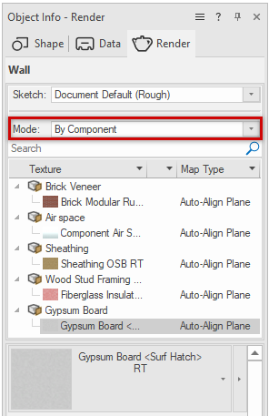
In the Texture browser, the wall components are listed in order, from the exterior component at the top of the list, to the interior component at the bottom.
Select the interior wall component at the bottom of the list in the Texture browser; the Resource Selector below the Texture browser shows the selected texture.
From the Resource Selector, select a different texture. The wall component's texture changes.
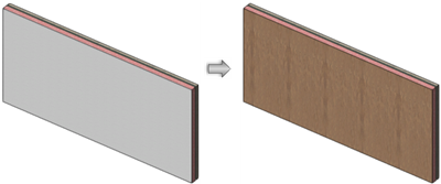
Instead of a bare gypsum board finish, this wall now has wood paneling
Plug-in objects
Many of the plug-in objects that are inserted with a tool, such as doors, cabinets, and soft goods (curtains) allow you to set their textures from the preferences/settings dialog boxes. Most plug-in objects, including the door used in this example, require a license for a Design Suite product, but some are available with Fundamentals.
Click the Door tool  , and then click Preferences
  on the Tool bar to open the Door Preferences dialog box. Keep the Door tool's default Unstyled selection.
Click the Materials and Classes pane.
You'll see a list of potential door parts, including interior and exterior sides of the door for some parts, each of which can be given a different texture. You can hold the Shift key to select multiple parts that should all have the same texture. The simple panel door used in the example doesn't have most of the parts.
Select the list row for Panels > Interior.
Below the list, click in the Texture field to select a texture from the Resource Selector. Enter "paint" in the search field, and select a paint color for the door's interior.
Place the cursor over the wall, until the wall highlights, and then double-click to insert the door.
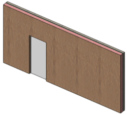
We now have a door with a gray painted interior inserted into a wood paneled wall.
3D modeling objects
3D objects that are manually modeled can also have texture applied, to the entire object and/or to a selected face. For this example, let's add a very basic stool beside the door.
From Top/Plan view, click the Circle tool  , and draw a circle beside the door.

With the Circle tool and the drawn circle still selected, return to Right Isometric view.
By not doing any more drawing actions before you change the view, you preserve Push/Pull mode  for the Circle tool.
Place the cursor over the circle. When it highlights, click, and then move the mouse upward to create an extrusion. Click again to set the extrusion height.
Click the Texture tool  , and click Apply to Object mode
  on the Tool bar.
Click Texture on the Tool bar to open the Resource Selector; enter "textile" in the search field, and select an upholstery texture for the stool.
Click the extrusion to apply the texture.
To give the top of the stool a different texture than the sides, with the Texture tool still selected, click Apply to Face mode  , and select a different textile from the Resource Selector.
Move the cursor over the top of the stool; the top is highlighted to indicate that's the face you'll apply the texture to.
Click to apply the texture to the top of the stool.
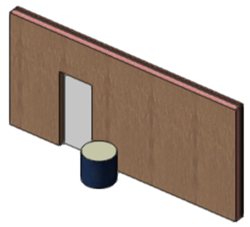
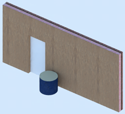
A sturdy stool provides a handy place to put shoes on before leaving the house
Add a light source
By default, Vectorworks drawings use ambient light, which works well for general visibility but doesn't cast shadows or show the contributions of individual light sources in the space. You can add light objects to the drawing to show how light fixtures in a room, or the sun, will look.
When you create a more sophisticated rendering with multiple light sources, we recommend turning off ambient light to see the full effect of the light objects in the drawing; see Setting lighting options for how to do that. But for this example, we don't want to make that change.
From Top/Plan view, click the Light tool  , and Point Light mode
  .
.
Click in the drawing to insert a light object.
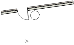
With the light selected, on the Object Info palette's Shape tab, make sure On and Cast Shadows are selected, and set the Z height of the light object, to place it about where a ceiling fixture would be.
Change back to Right Isometric view; and make sure the render mode is set to Shaded.
You should see the glow of the light, which will vary in intensity across the wall.
If the stool isn't casting a shadow against the wall, click the icon  for Current Render Mode Options on the View bar to open the Shaded Options dialog box, and click Shadows; make sure On ground only is turned off.
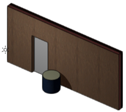
While you're working on a design layer, the light object remains visible by default, so you can select it if you need to move it or change settings. You can change this setting in Vectorworks preferences.
Set the view
Vectorworks provides several standard views, but you can also set a custom view. To change the drawing view, do one of the following:
Select a standard view from the Current View/Standard Views list on the View bar or the Onscreen View Control cube. If you select a rear standard view, you'll get a peek at the wall style's exterior texture.
Use the Onscreen View Control cube or the Flyover tool  to dynamically change the view.
Use the mouse wheel button and Ctrl/Control key to set a custom view
There are several other ways to set views in Vectorworks, as described in the Viewing the drawing section of the Vectorworks help system.
Choose a rendering mode
The rendering mode you choose for your scene makes a huge difference it how it looks. It can range anywhere from photorealistic to a much looser sketch appearance, and many looks in between. Typically, for a large and complex design, you should make changes to the rendering modes within a viewport, but for this small example, let's play with rendering modes directly in the design layer, to see what happens.
From the Current Render Mode list on the View bar, select different modes, to see how they compare to Shaded mode, as shown in the 3D graphics above. You can also change some of the render mode options for each rendering mode, by clicking the icon beside the list. Here are some examples of the drawing, using the Right Isometric standard view and a variety of rendering modes.
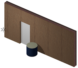
Final Quality Renderworks
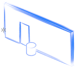
Artistic Renderworks, set to Pencil (Rough Sketch) style in the Artistic Renderworks Options dialog box
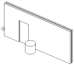
Hidden Line
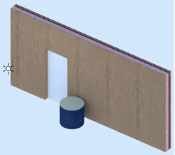
Renderworks Style of Redshift Interior Final
Now that you know the basics, you can explore and learn more about rendering your designs. The Concept: Best rendering practices help topic is great place to start to extend your knowledge.
