Truss properties
These settings are available in the following locations:
Object Info palette (editing an object)
Object Properties dialog box (editing an object; right-click the object and select Properties from the context menu)
Other truss parameters must be edited from the Truss Properties dialog box; see Setting custom truss parameters.
Click to show/hide the parameters.Click to show/hide the parameters.
|
Parameter |
Description |
|
Trim Height |
Specifies the height of the lowest point on the object; it is the absolute height of the truss compared to the ground level. Trim height could be different from the Z height if the object is rotated with its its roll or hanging angles, or if its insertion point is not the lowest part of the object. |
|
Orientation parameters |
To orient the truss, Vectorworks applies the Roll, Hanging Angle, and Rotation settings in the this order |
|
Roll |
Rotates the truss object on its X axis; the truss rotates around its insertion point |
|
Hanging Angle |
Rotates the truss object on its Y axis; the truss rotates around its insertion point |
|
Rotation |
Rotates the truss object on its Z axis; the truss rotates around its insertion point |
|
Properties |
|
|
Symbol |
Displays the truss symbol |
|
Type |
Displays the truss type, manufacturer, or catalog identification number |
|
Name |
Identifies the truss section; if the truss is converted to a hanging position, the name of the hanging position displays automatically |
|
ID |
Unique identifier for truss calculations and labels; if blank, a value is automatically assigned when calculations are run (Braceworks required) |
|
Position Name |
Enter a name for identification and reporting purposes. When the truss is used as a hanging position, this name automatically populates the Position field of any attached load objects. |
|
Height/Width |
Displays the height and width values of the truss |
|
Total Weight |
Sets the total gross weight of the truss; corner trusses are considered as point loads in calculations, while all other truss types are considered as distributed loads |
|
Distributed Weight |
Displays the weight per unit of length for the truss |
|
Length (straight or curved truss only) |
Displays the length of the truss |
|
Hinge Angle (hinge truss only) |
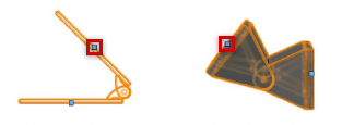
Sets the angle between the hinge parts. You can manually adjust the hinge angle by moving the control points on the hinge truss.
Book hinges display control points in 2D views; center hinges display control points in 3D views |
|
Insert Locking Pipe (book hinge only) |
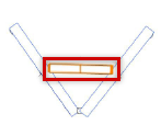
Inserts a lighting pipe to connect and lock the hinge parts. The lighting pipe is considered as a separate object in Braceworks calculations.
Lighting pipe object |
|
Cross Section |
Displays the cross section unique ID number, when a cross section file has been associated with the truss as described in Specifying cross section data. Cross section information is required for valid calculations; if there is no identified cross section, calculations will not be complete. |
|
Connectable with |
Displays the ID of rigging objects that can be connected to this truss, forming a structural system |
|
Truss System |
Displays the name of the truss system to which the truss belongs, along with the truss line number |
|
Display |
|
|
Draw 3D Only |
Hides the 2D-only portion of the object, making it easier to view and rotate in 3D views |
|
Center line |
In Top/Plan view, displays the truss center line; some load objects are attached at the truss center line |
|
Actions |
See Modifying trusses and systems for parameter descriptions |
|
Equipment Subparts |
Lists the subparts that make up the object. These subparts are counted and reported separately in equipment and inventory lists. The parameters must be selected for display for this type of object in Spotlight preferences: Inventory pane. |
|
Equipment Virtual Parts |
Virtual parts are associated with an object and are reported in equipment and inventory lists, but do not display in the drawing. After adding virtual parts, they are listed in the Object Info palette. |
|
Edit Virtual Parts |
Opens the Virtual Parts dialog box to add virtual parts to the object; see Managing virtual parts and independent virtual parts |
|
Assign Sources |
Opens the Assign Sources dialog box to assign the object and its subparts and virtual parts to an inventory source; see Assigning equipment to an inventory |
Setting custom truss parameters
Some truss parameters depend on manufacturer data or custom specifications. These parameters can be viewed and edited from the Truss Properties dialog box; see Modifying truss symbol data or Creating a custom truss symbol.
Different parameters display for straight, corner, hinge, and circular (curved) trusses. Select the truss type from the Geometry Type list, and edit the parameters as needed.
Click to show/hide the parameters.Click to show/hide the parameters.
|
Parameter |
Description |
|
Object Data |
|
|
Type |
Enter a truss system name |
|
Name |
Specify a catalog name for the truss element |
|
Length (L) (straight truss only) |
Enter the installation length |
|
Diameter (D) (circular truss only) |
Enter the outer diameter of the circular truss |
|
Angle (A) (circular truss only) |
Specify the arc angle of the truss from the start point to the end point |
|
Insertion point is center point (circular truss only) |
Indicates that the center point of the truss is also its insertion point |
|
Total Weight |
Enter the total weight of the truss |
|
Distributed Weight (straight or circular truss only) |
Displays the distributed weight of the truss; this is calculated automatically based on the Length and the Total Weight. Changes here also affect the Total Weight value. |
|
Vertical symbol (straight truss only) |
Indicates that the symbol will be inserted as a vertical truss; if deselected, a horizontal truss is assumed |
|
Minimum/Maximum Angle (A) (hinge truss only) |
Specify the minimum and maximum angle for the hinge truss |
|
Cross Section Data |
|
|
UID |
Displays the ID of any currently selected cross section |
|
Change Cross Section |
Opens the Cross Section dialog box to select a cross section file to associate with the truss, as described in Specifying cross section data |
|
Height/Width |
If a generic (rigid) cross section was selected, or a cross section is not specified, enter the total installation height and width of the truss; otherwise, the height and width from the selected cross section display |
|
Connectable with |
Specifies the Type of cross section that the truss can connect to. The truss must be connectable with its own type. To list more than one cross section, separate them with semi-colons. |
|
Connection |
|
|
Start/End (straight, hinge, or circular truss only) |
Select the type of connection for each end of the truss, or select No Connection; see Concept: Creating a connected rigging system. At insertion, Auto Connect mode uses the selections for proper truss connection. |
|
Roll Angle (straight, hinge, or circular truss only) |
Sets the connection angle for triangle trusses. The truss object is rotated on its X axis. Up-pointing triangle trusses should be set to 0 (zero) degrees; down-pointing triangle trusses should be set to 180 degrees.
Down-pointing truss at 180 degrees and up-pointing truss at 0 degrees |
|
Geometry |
Displays a typical truss to show the parameter locations |
|
Corner Type (corner truss only) |
Select the type of corner geometry; the diagram adjusts to display the required parameters |
|
Hinge Type (hinge truss only) |
Select the type of hinge geometry; the diagram adjusts to display the required parameters |
|
Parameter values (corner or hinge truss only) |
Depending on the selected Corner Type or Hinge Type, different parameters are required. The diagram indicates where the parameters are located. For Corner Type: Length values are required for typical corners. Up to six points can be defined for Custom types. Specify the coordinates at the middle of the truss where the center lines cross. Then select the corners of the connection points on the truss, and specify their coordinates relative to the insertion point. |
|
Edit Magnets in Symbol |
Opens the truss symbol in Object editing mode to adjust the magnets; see Adjusting magnets |