 Editing lighting devices
These settings are available in the following locations:
Object Info palette (editing an object; select the object and edit from the Object Info palette, or right-click the object and select Properties from the context menu)
Lighting Device dialog box (editing an object; click Edit from the Object Info palette of a selected lighting device, or right-click the object and select Edit from the context menu)
Light Source Object Info palette (editing an object; right-click the object and select Edit Light from the context menu; see Light source properties)
Once lighting devices have been inserted, many of the parameters can be changed from the Object Info palette or Lighting Device dialog box, and the color, numbering, alignment, and other options can be set. Change advanced light properties, including turning the associated light source on, by editing the light source embedded within the device; see Advanced light properties. To display the cell parameters from a multi-cell lighting device, select the desired cell in the Edit Cell field.
First, select the lighting device or devices to edit.
Selecting lighting devices
Before editing lighting devices, you need to select them. When you need to edit many lighting devices at once, use context menu commands to select devices by certain criteria. You can select all the lighting devices with the same instrument type, position, rigging object location, or focus point.
|
Context menu command |
Description |
|
Select Lighting Devices by Instrument Type |
Right-click on a device that has the desired instrument type, and select the command. All lighting devices of that type are added to the current selection. |
|
Select Lighting Devices by Position |
Right-click on a device on the desired lighting position, and select the command. All lighting devices at that position are added to the current selection. |
|
Select Lighting Devices on Rigging Object |
Right-click on the rigging object/hanging position, and select the command. All the lighting devices on that rigging/hanging object are added to the current selection. |
|
Select Focused Lighting Devices |
Right-click on the focus point, and select the command. All the lighting devices assigned to that focus point are selected in the drawing; all other objects are deselected. |
Editing from the Object Info palette
Lighting device parameters can be viewed and edited from the Object Info palette. Select the parameters and parameter groups you want to display from the Spotlight preferences: Lighting Devices: Parameters pane. This pane also controls which parameters can be set independently for accessories and for the cells in multi-cell devices.
If your file was created in a previous version of Vectorworks, any default lighting device parameters that were removed from the current version can still be accessed on the Spotlight preferences: Lighting Devices: Parameters pane. You can display these parameters on the Object Info palette or remove them from the file. Any customized lighting device parameters maintain their custom values but update their default values to match the current version.
To display the accessory and/or hardware parameters from the associated lighting device or cell, select the desired accessory/hardware in the Edit Accessory field. When a value other than <None> is selected, the parameters of the specified accessories/hardware are shown, instead of the lighting device parameters. The Device Type field indicates whether an accessory, hardware, or lighting device is being edited.
The parameters below are described in terms of lighting devices, but the same behavior applies to accessories and hardware unless otherwise noted.
DMX patching may change the lighting device (and accessory) parameters as conflicts are resolved; see DMX patching.
For a custom lighting device symbol without an information record attached, enter the required parameters (see Attaching the Light Info Record and EntEquipUniversal record). An entry is not required for every field.
Click to show/hide the parameters.Click to show/hide the parameters.
|
Parameter |
Description |
|
XYZ/IJK Location/Rotation |
Changes the lighting device’s location and rotation; the labels rotate with the lighting device unless Right-Reading is selected in the Label Legend Manager (see Formatting the label legend layout). In a 3D view, if a lighting device is focused, the lighting device rotates automatically to point at the focus. A lighting device and its accessories move and rotate together. For this reason, the position and orientation of an accessory relative to its associated lighting device cannot be changed from the lighting device Object Info palette. To adjust the accessory position in 2D and 3D views, use Accessory edit mode instead. |
|
Edit |
Opens the Lighting Device dialog box, to edit the parameters of one or more lighting devices; see Editing from the Lighting Device dialog box |
|
Edit Accessories and Hardware |
Opens the accessory edit mode, to edit accessories and hardware in 2D and 3D views; see Accessory edit mode |
|
Symbol Name |
Displays the name of the symbol used to create the lighting device, accessory, or hardware |
|
Instrument Type |
Displays the specific type of lighting device |
|
Replace Lighting Device/Replace Accessory/Replace Hardware |
Opens the Resource Selector; double-click a resource to select it. Replace Accessory displays when the selected part of the lighting device displayed in the Edit Accessory list is an accessory. Replace Hardware displays when the selected part of the lighting device displayed in the Edit Accessory list is hardware. Select the accessories or hardware to replace from the Edit Accessory list. If <All> accessories/hardware are selected for editing, all the accessories/hardware on the selected device(s) are replaced by the chosen resource. If a specific accessory or hardware is selected for editing, only that accessory or hardware is replaced. If one of the selected lighting devices is a multi-cell, you can only replace the accessories or hardware on the cell(s) specified in the Edit Cell field. |
|
Edit Accessory (accessories and/or hardware required) |
Choose whether the Object Info palette displays the lighting device, accessory, or hardware parameters, and select which accessories/hardware display their parameters. The Device Type indicates whether lighting device, accessory, or hardware parameters are being edited. For multi-cell lighting devices, the options depend on the Edit Cell selection. If all cells are selected, all or none of the device’s accessories/hardware can be edited. If a single cell is selected, the accessories/hardware specific to that cell can be edited. <None>: Displays the parameters of the lighting device, not its accessories or hardware. <All>: Displays the parameters of all the attached accessories and/or hardware. <Multiple values> displays for parameters that are not identical for all accessories and/or hardware. <All Accessories>: Displays the parameters of the specified accessory. The accessories are listed by their index number - accessory symbol name. <All Hardware>: Displays the parameters of the specified hardware. The hardware are listed by their index number - hardware symbol name. |
|
Edit Cell (multi-cell lighting devices only) |
Select which cell displays its parameters, or select <All> to display the parameters of all cells in the device. <Multiple values> displays for parameters that are not identical for all cells. The cells are listed by their index number - color - channel. |
|
Fixture Mode |
Select the fixture mode of the lighting device (or search for the mode by entering text in the search box), for export to an external program like Vision, or select None. The DMX Footprint is set automatically by the selected mode and cannot be edited; however, if a GDTF Fixture Mode is specified too, this mode will set the DMX Footprint instead. For more information about fixture modes, see Selecting a fixture mode. |
|
GDTF Fixture Mode |
Select the GDTF fixture mode of the lighting device; search for the GDTF file by entering text in the search box. The DMX Footprint is set automatically by the file and cannot be edited. For more information about .gdtf files, see Attaching GDTF data. |
|
GDTF Fixture |
Displays the GDTF file that is associated with the lighting device |
|
Edit GDTF Data |
Opens the GDTF Fixture Builder, for editing GDTF data directly in Vectorworks; see Editing GDTF data |
|
Use GDTF geometry |
When a valid GDTF file is selected, this option replaces Vectorworks symbol geometry with the geometry specified in the GDTF resource. This mode is enabled by default when you import a .mvr file that creates a new lighting device from a GDTF resource. |
|
DMX Footprint |
Displays the number of control channels used by the lighting device. If the lighting device has a specified Fixture Mode or GDTF Fixture Mode, the number of channels is automatically assigned. If fixture modes are specified for both Vision and GDTF, the GDTF file sets the number of channels. |
|
Purpose |
Specifies the purpose of the lighting device |
|
Position |
Displays the name of the associated rigging object, if the lighting device is attached. For methods to attach loads, see Making the attachment. |
|
Unit Number |
Identifies the lighting device location on the hanging position or rigging object |
|
Channel |
Specifies the channel number, or channel "name," of the lighting device. This name identifies the device when power patching; see Power patching the electrical system. |
|
Universe/Address |
Specifies the universe and address, separated by a front slash separator; the separator can be changed as described in Spotlight preferences: Lighting Devices: Parameters pane |
|
Universe |
Specifies the universe assigned to the lighting device; see Spotlight preferences: Universes pane |
|
DMX Address |
Specifies the DMX address assigned to the lighting device; see Spotlight preferences: Universes pane. To unpatch the lighting device, set this value to 0 (zero) to remove the universe, address, and DMX address information, or unpatch the lighting device from the Patch dialog box; see DMX patching. In files created prior to version 2020, this field may also display as User U Address to ensure compatibility. |
|
Absolute Address |
Specifies the address of the lighting device without a universe indicator; for example, universe 2/address 1 is absolute address 513. To unpatch the lighting device, set this value to 0 (zero) to remove the universe, address, and DMX address information, or unpatch the lighting device from the Patch dialog box; see DMX patching. In files created prior to version 2020, this field may also display as User Address to ensure compatibility. |
|
Dimmer |
Specifies the dimmer number of the lighting device |
|
Circuit Number |
Indicates the circuit number where the lighting device is plugged in |
|
Circuit Name |
Specifies the name of bundled circuit group |
|
Color |
Specifies the gel color number according to manufacturer code, RGB values, color name from the file, or web (hex) codes; when the light associated with the lighting device is turned on, Color specifies the actual light color. Use + between color numbers to indicate combinations of two or more colors. See Lighting device color. The color setting can affect the display of the lighting device color, depending on the Spotlight preferences; see Spotlight preferences: Lighting Devices: Classes and Color pane. |
|
Frame Size |
Indicates the dimensions of the color cut |
|
Gobo 1 |
Indicates the gobo texture number for the first gobo. Specifying the gobo texture by clicking Edit in the Object Info palette provides a graphical method of selecting gobo textures. |
|
Gobo 1 Rotation |
Sets the rotation angle of gobo texture 1 |
|
Gobo 2 |
Indicates the gobo texture number for the second gobo |
|
Gobo 2 Rotation |
Sets the rotation angle of gobo texture 2 |
|
Use Legend |
Select the label legend to apply from the list of label legends in the file (see Label Legend Manager) |
|
3D Legend View |
When the label legend includes 3D labels, select the view for the labels when displaying the drawing in a 3D view. Select Screen Aligned to always view the labels aligned with the screen plane (in a viewport, screen aligned labels match the view). After changing the view, click Refresh Labels to obtain the selected legend view, or select the Refresh Lighting Devices command. Easily copy the label legend positions to selected lighting devices by Changing the label legend properties of a selection. |
|
Flip top and bottom 3D legend |
Mirrors the 3D label along the X axis of the lighting device (for example, a label legend that displays at the top of the device displays on the bottom instead) |
|
Flip left and right 3D legend |
Mirrors the 3D label along the Y axis of the lighting device (for example, a label legend that displays to the right of the lighting device displays on the left instead) |
|
Rotate 3D legend with Z rotation |
Matches the 3D label legend views with the lighting device’s rotation |
|
Flip front and back 2D legend |
Mirrors the label legend along the X axis of the lighting device (a label legend that displays in front of the lighting device displays behind it instead) |
|
Flip left and right 2D legend |
Mirrors the label legend along the Y axis of the lighting device (a label legend that displays to the right of the lighting device displays on the left instead) |
|
Custom plan rotation |
Select this option to specify a rotation angle for Top/Plan view that is independent from the device’s Rotation parameter. When this option is selected, specify the Plan Rotation angle. |
|
Zoom |
Enter the zoom percentage, or use the slider to set the value. This controls the beam and field angle for lights that can zoom. If the light has an oval beam, it is considered to be a light that cannot zoom; set specific field and beam angles instead. |
|
Field Angle |
Displays the angle for zoomed lights, or sets the vertical field angle of the lighting device's light beam for lights that cannot zoom |
|
Field Angle 2 |
Displays the angle for zoomed lights, or sets the horizontal field angle of the lighting device's light beam for lights that cannot zoom |
|
Beam Angle |
Displays the angle for zoomed lights, or sets the vertical beam angle of the lighting device's light beam for lights that cannot zoom |
|
Beam Angle 2 |
Displays the angle for zoomed lights, or sets the horizontal beam angle of the lighting device's light beam for lights that cannot zoom |
|
Focus |
Names the focus point object assigned to the lighting device. The focus point must be defined first (see Creating a focus point object). If the Pan and Tilt values are adjusted later, the lighting device loses its association with the focus point. |
|
Draw beam |
Draws an accurate wireframe representation of the light beam; the light beam is drawn based on the lighting device parameters, and can be used to check whether the stage and focus areas have been adequately lit (see Drawing light beam representations). Spotlight preferences setup can globally specify the appearance and display of the elements in the light beam (angles and centerline). |
|
Draw beam as 3D solid |
Generates a light beam that appears solid when rendered |
|
Use vertical beam |
By default, draws the wireframe beam in a vertical orientation when possible, when either Draw beam or Draw beam as 3D solid is selected. When deselected, the beam is usually drawn in a horizontal orientation. |
|
Show Beam at |
In a 2D view, select whether to draw the beam as it crosses the focus, at the falloff distance as projected through the focus, or in both areas |
|
Refresh Labels |
Refreshes lighting device label contents if parameter changes have been made, or 3D label positions if the view has changed |
|
Brightness (%) |
Sets the light source brightness; enter a percentage or use the slider to set the value. A value over 100% can be entered. |
|
Use emitter |
Specifies the light’s actual brightness and color temperature based on the Brightness Value multiplied by the Brightness (%). Leave this option deselected to use the light as a simple light source, with its baseline light source value multiplied by the Brightness (%). If the light has an attached GDTF definition, the emitter brightness is set from the GDTF file when Use GDTF geometry is selected. |
|
Brightness Value |
Enter the brightness value; units are set in the Lighting Device dialog box |
|
Falloff Distance |
Specifies how far the wireframe light beam is drawn beyond the focus |
|
Lamp Rotation Angle |
Indicates the rotation angle of the virtual elliptical light source, from 0 to 90° |
|
Pan |
Enter the pan angle, or use the slider to set the value; this controls the lateral rotation angle of the lighting device (range: +/- 180º). If a focus point is assigned, this value automatically updates. |
|
Tilt |
Enter the tilt angle, or use the slider to set the value; this controls the vertical rotation angle of the lighting device (range: +/- 180º). If a focus point is assigned, this value automatically updates. |
|
Invert pan/Invert tilt |
Inverts the lighting device's pan and tilt directions, including when running Showcase |
|
Shutter parameters |
Enter the shutter depth/angle, or use the slider to set the value. This controls the angle and depth of top, left, right, and bottom shutter cuts. Each shutter is located at 90º intervals around the lighting device, and angles can be adjusted within a range of +/- 45º. The shutter depth ranges from 0 to 100%, with 100% cutting through the center of the light source. |
|
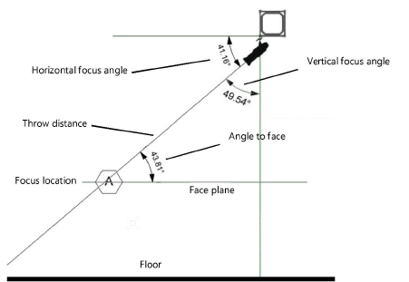
Throw Distance |
Controls the distance from the lighting device to its focus location. If a focus point is assigned, this value automatically updates. |
|
Vertical Focus Angle |
Displays the focus angle up from vertical
|
|
Horizontal Focus Angle |
Displays the focus angle down from horizontal |
|
Angle To Face |
Displays the angle at which the light hits the face plane of the lit subject at the focus |
|
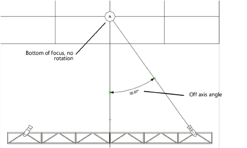
Off Axis Angle |
Displays the angle from the centerline of the focus to the lighting device. The bottom of the focus is the centerline; if a focus point is used, move the focus point to change the centerline location.
|
|
Weight |
Specifies the lighting device weight. For lighting devices with accessories and/or hardware, use the Edit Accessory field to select each accessory or hardware and then specify its weight. The weight of the lighting device and all accessories and/or hardware is combined to calculate the Total Weight of the lighting device. |
|
Load Information |
A lighting device is considered a point load in Braceworks calculations; if the insertion point is on a structural element, it is considered to be a load on that structure. Load information is used for Braceworks calculations and reports (Braceworks required). |
|
Include in calculations (Braceworks required) |
Includes the lighting device in Braceworks calculations; deselect to exclude the device from participating in structural calculations |
|
Load Group Name |
The load category is always Light for lighting devices |
|
Load ID |
Enter a unique ID for the load for informational use in reports |
|
Load Name |
Identifies the object in load calculations; normally the object name is used |
|
Total Weight |
Enter the total weight of the object. For lighting devices with accessories and/or hardware, this parameter displays the total weight of the device and its accessories and/or hardware and it cannot be edited. |
|
Position |
Enter the load position |
|
Device Type |
Displays the type of object that is selected. Normally, lighting devices are Light device types (Moving Light, Device, Practical, SFX, Power, and Other are also considered Light types). Accessories such as color frames, barn doors, top hats, and clamps are Static Accessory types. Accessories that require a control channel, such as color scrollers, are Accessory types. |
|
Wattage |
Indicates the power consumed by the lighting device |
|
Voltage |
Specifies the voltage of the lighting device |
|
Breaker ID |
Provides the power distribution identifier of the lighting device |
|
Time |
Approximates the time required to work with the device, useful in reports |
|
Cost |
Specifies the rental cost of the device, useful in reports |
|
System |
Specifies the letter describing the control system (Lightwright-compatible parameter) |
|
User Field 1-6 |
Provides user-defined fields; use these extra fields to keep track of any desired data (see Spotlight preferences: Lighting Devices: Parameters pane) |
|
Mark |
Provides a user-defined label (Lightwright-compatible parameter) |
|
Power Information |
A lighting device can be power patched within the electrical system; see Power patching from the Object Info palette. Power information is used for power calculations and reports. |
|
Select Range |
The socket connection parameters are displayed in sets of seven. Select which set of sockets to display for editing. The sets are numbered according to the input stacking order. |
|
Power In |
Displays the patching information (connectors) for the lighting device. You can search for and select a new socket for the input connection; once connected, the connection displays at the top of the list. |
|
Consumption |
Displays the amount of power required by the device |
|
Voltage |
Displays the voltage required by the input connection |
|
Connector |
Displays the connector used for the input connection |
|
Select Power Source |
Selects the connected input source of power for the lighting device in the drawing area |
|
Link Through |
Displays an additional output connector that enables lighting devices to be daisy chained without twofers, for lighting device symbols without electrical components. You can search for and select a new link through for the output connection; once connected, the connection displays at the top of the list. |
|
Voltage |
Displays the voltage required by the output connection |
|
Connector |
Displays the connector used for the output connection |
|
Equipment Subparts |
Lists the subparts that make up the object. These subparts are counted and reported separately in equipment and inventory lists. The parameters must be selected for display for this type of object in Spotlight preferences: Inventory pane. |
|
Equipment Virtual Parts |
Virtual parts are associated with an object and are reported in equipment and inventory lists, but do not display in the drawing. After adding virtual parts, they are listed in the Object Info palette. |
|
Edit Virtual Parts |
Opens the Virtual Parts dialog box to add virtual parts to the object; see Managing virtual parts and independent virtual parts |
|
Assign Sources |
Opens the Assign Sources dialog box to assign the object and its subparts and virtual parts to an inventory source; see Assigning equipment to an inventory |
Editing from the Lighting Device dialog box
The Lighting Device dialog box allows you to edit the lighting parameters of one or more lighting devices, including the cell-specific parameters of multi-cell devices. You can view and change the lighting device properties and the light source properties, as well as the device specifications for visualization.
Many of the parameters listed in this dialog box are also available in the Object Info palette. Only the parameters that are unique to the Lighting Device dialog box or have special behavior are listed here.
To edit the properties of a lighting device:
Select one or more lighting devices.
From the Object Info palette or the context menu, click Edit, or simply double-click a single device. The Lighting Device dialog box opens.
If multiple lighting devices are selected, they display in a list on the left.
If one or more multi-cell devices are selected, a list of the cells displays.
If any of the selected devices have accessories and/or hardware, a list of the accessories and/or hardware displays.
Lighting Device: Overall
Select items from the Lighting Devices and/or Cells and Accessories lists to view and edit their parameters.
If multiple items are selected, the parameters display the shared values only.
Click to show/hide the parameters.Click to show/hide the parameters.
|
Parameter |
Description |
|
Lighting Devices (multiple selection only) |
Displays the selected lighting devices, sorted by channel number. Select one or more lighting devices to view their parameters, or select <All selected> to view the parameters of all the lighting devices in the multiple selection. You can also sort by Instrument Type, Position, or Purpose; click a column heading to sort in ascending or descending order. |
|
Cells (multi-cell lighting devices only) |
Displays the cells in the selected lighting device. If multiple lighting devices were selected, the cells in the device that is currently selected in the Lighting Devices list are displayed. Select one or more cells to view their parameters, or select <All cells> to view the parameters of all the cells in the selected lighting device. |
|
Accessories (accessories and/or hardware required) |
Displays the accessories and/or hardware attached to the selected lighting devices or cells. <None>: Displays if any selected lighting device or cell has accessories and/or hardware. Select this option to view the parameters of the selected devices or cells, instead of their accessories and/or hardware. <All accessories>: Displays if any selected lighting device or cell has accessories and/or hardware. Select this option to view the parameters of all the accessories and/or hardware attached to the selected devices or cells. Accessory: Displays if a single selected lighting device or cell has accessories and/or hardware, or if each lighting device or cell in a multiple selection has the same number of accessories and/or hardware. Select this option to view the parameters of a specific accessory or hardware. If each selected lighting device or cell has the same number of accessories and/or hardware, but the accessories and/or hardware are different (for example, one device has a top hat while the other has a gobo holder), the accessories’ index numbers display in the list with a Symbol Name of <Multiple values>. Select one of these options to view the parameters of all accessories and/or hardware that have the same index number. |
Lighting Device: Properties tab
Click to show/hide the parameters.Click to show/hide the parameters.
|
Parameter |
Description |
|
Displays the name of the hanging position. Select a different hanging position, or select <Custom> and enter the name of an object to use as the hanging position. Enter text in the search box to filter by name. |
|
|
Symbol Name |
Opens the Resource Selector to select a different lighting device symbol, accessory, or hardware; double-click a resource to select it |
|
Get Data from Symbol |
Obtains the light information from the Light Info Record attached to the symbol definition |
Lighting Device: Light Information tab
Click to show/hide the parameters.Click to show/hide the parameters.
|
Parameter |
Description |
|
Focus |
Controls the focus settings |
|
Displays the name of the focus point, if one is assigned. Select a different focus point, or select <Custom> and enter the name of an object to use as the focus point. Enter text in the search box to filter by name. |
|
|
Beam |
Controls the settings for light beam representations |
|
Physics |
Controls the settings for wattage, voltage, and frame size |
|
Render |
Contains many of the parameters described in Light source properties |
|
On/Off |
Shows or hides the light produced by the light source. This setting can also be accessed from the light context menu: right-click on the light, and select Turn On or Turn Off. Lighting devices can be inserted on or off by default; see Spotlight preferences: Lighting Devices: Parameters pane. |
|
Gobo 1 |
Enables a Resource Selector. Click the Resource Selector to select a texture for the first gobo; double-click a resource to activate it. |
|
Gobo 2 |
Enables a Resource Selector. Click the Resource Selector to select a texture for the second gobo; double-click a resource to activate it. |
|
Comments |
Provides notes about how the lighting device is configured in the Vision program |
Lighting Device: Shutters tab
Specify the depth and angles for the top, left, right, and/or bottom shutters. Each shutter is located at 90° intervals around the lighting device, and angles can be adjusted within a range of +/- 45°. The shutter depth ranges from 0 to 100%, with 100% cutting through the center of the light source.
Lighting Device: User Data tab
User data fields and any default values display here. You can edit the default values by selecting a field name and entering new data in the Value column.
Lighting Device: Wheels tab
Click the Wheels tab to control lighting devices used for previsualization in Showcase, or sent to (or exported to) a lighting console or visualizer. When the lighting device has a Fixture Mode, the gobo, color, and animation data for the lighting device can be set here.
If multiple devices are selected, these tabs display the shared data only. Some fixture modes are specific to the Vision program, while others are available in General Device Type Format (GDTF); see Workflow: Previsualization with Spotlight. The devices must have the same Fixture Mode and the same gobo, color, or animation data in order to be edited simultaneously.
The default specifications are set according to the Fixture Mode specified in the Object Info palette. Customizations to the data are applied to the lighting device and show in the MVR file upon export; see Exporting MVR files. On the Wheels tab, click Reset Wheel Defaults to restore the default data for the lighting device based on the Fixture Mode.
Click to show/hide the parametersClick to show/hide the parameters
|
Parameter |
Description |
|
Data |
Select whether to display GDTF or LIT (Vision) data |
|
Wheels list |
Lists the wheels, in hierarchical order, from the selected accessory of the lighting device: Wheel: Displays the name of the gobo, animation, or color wheel group and its slot locations. Each Slot location displays any selected item for the slot. Click the disclosure arrow next to the wheel name to quickly expand or collapse the group. Slot: Displays the gobo, animation, or color slot location in the wheel. Name: Displays the name of the gobo, animation, or color in the slot. Color: Selects the custom colors to load into the slots of the wheel. To select or change the color for the slot, click the Color column and click the color box to select the color (see Applying colors). The Color name changes to Custom and a preview of the custom color and new Color Value displays. Color Value: Displays the RGB color value in the slot. |
|
Reset Wheel Defaults |
Reverts to the default wheel data |
|
Select Image File |
For gobo or animation wheels, a preview on the right displays when available. Click Select Image File and select a gobo image from the Select Gobo dialog box or animation image from the Select Anim dialog box to change the image for the slot. |
