Drawing doors, windows, and assemblies
|
Mode |
Tool |
Tool set |
Shortcut |
|
Interactive Sizing Insertion
|
Door
Window
Door and Window Assembly
|
Building Shell |
Door tool Alt+Shift+D (Windows) Option+Shift+D (Mac) Window tool Shift+D (Windows) Option+Shift+W (Mac) |


Doors, windows, and assemblies can be placed quickly simply by drawing a rectangular shape in the desired location, using either Corner to Corner or Center to Corner submode. You don't need to define the Width, (and for 3D views) Height, and/or Z location dimensions in advance. The clicks that define the Width and Height parameters are coordinated to the object's selected Size Reference. You can size the object and align it with adjacent architectural features as needed. Snapping is available to ensure proper placement.
Alternatively, to insert a door, window, or assembly by clicking within the drawing, see Inserting doors, windows, and assemblies; this method uses all the object's preferences, including the height and width settings. To create an assembly from existing doors and windows, or from a closed 2D shape, see Creating a door and window assembly from existing objects.
For styled objects, only dimensions set by instance can be defined by drawing. You can draw to set instance dimensions, and snap or align an object edge with other geometry, but parameters set by style are constrained. The preview reflects the constraints, and dimensions set by style are grayed on the Data bar. To use parameters associated with an object style, but retain the power to draw a custom size, select the desired style, and then click Convert to Unstyled in the preferences dialog box before drawing the door.
Drawing doors, windows, and assemblies in a 3D view
In a 3D view, you can draw an object that extends outside the wall it is being placed into; for example, you can draw a tall assembly in an atrium or a door along a stair, and place the object to span two walls. You can also draw an object that isn't placed in a wall.
A door/window/assembly can only be placed into a single wall object, so if an object spans two walls, you will need to draw an empty object opening in the second wall, and snap it to the original object's dimensions to create the hole in the second wall.
To draw a door, window, or assembly in a 3D view:
Click the tool and mode, and either Corner to Corner or Center to Corner submode.
Do one of the following:
Click [Object] Style on the Tool bar to select a resource from the Resource Selector.
Individual manufacturer catalog items cannot be selected using the Resource Manager; see Concept: Plug-in object styles and catalog items.
Click Preferences to open the preferences dialog box and specify the tool's default parameters (see Door settings, Window settings, or Door and window assembly settings); there is no need to set the Width or Height, which are adjusted to match the drawn object.
The parameters can be edited later from the Object Info palette.
Click to place either the first side or the center of the object, according to the selected submode; the object previews. When Wall Insertion mode is on, the wall highlights as you move the cursor over it, and the movement is constricted to the wall plane. Snapping lines on the wall display the current Height and (for windows and assemblies) Elevation In Wall settings; these lines are for snapping and reference only, and do not limit where you can place the object.
For hinged doors and windows, the first click defines the hinge side, and the second click places the frame side. In 3D views, the object opens out from the face it is drawn on. Non-hinged windows are inserted in their default orientation when drawn from left to right, and mirrored when drawn from right to left. The orientation can be changed using the interactive handing controls in Top/Plan view (recommended) or flipped from the Object Info palette.
The following constraints can be applied as needed:
To constrain the object to be square, press and hold the Shift key while drawing.
To constrain the object to the golden ratio, press and hold Ctrl-Shift (Windows) or Cmd-Shift (Mac) while drawing.
To constrain the bottom of the door to the Z location of 0, press the Alt key (Windows) or Option key (Mac) before you click to place the bottom of the door.
To constrain either the top or bottom of the window or assembly to the elevation snapping line, press the Alt key (Windows) or Option key (Mac) before either click; the edge placed while the key is pressed is constrained. If the Elevation in Wall is set by style, the object's Z location adjusts as needed to reflect the drawn window placement.
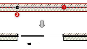
Move the mouse to the desired location, and click a second time to finish placing the door.
A door, window, or assembly is drawn in the location and of the size indicated; the Width, Height, and any relevant handing parameters are set to match the drawn object, and the Z location is adjusted if necessary.
Corner to Corner insertion of a door
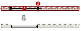
Center to Corner insertion of a window
Optionally, create a style resource from an unstyled object (see Custom plug-in object styles with catalog options).
Drawing doors, windows, and assemblies in Top/Plan view
Doors, windows, and assemblies drawn in Top/Plan view control the Width; other dimensions are those set by the style or preference. When the object is inserted into a wall, its path is constrained to the wall's path. It is also possible to draw an object without inserting it in a wall.
Although you can't draw the object's height in Top/Plan view, you can tab into the floating Data bar and enter the height.
To draw a door, window, or assembly in Top/Plan view:
Click the tool and mode, and either Corner to Corner or Center to Corner submode.
Do one of the following:
Click [Object] Style on the Tool bar to select a resource from the Resource Selector.
Click Preferences to open the preferences dialog box and specify the tool's default parameters (see Door settings, Window settings, or Door and window assembly settings); there is no need to set the Width.
The parameters can be edited later from the Object Info palette.
When Wall Insertion mode is on, the wall highlights as you move the cursor over it, and the object's path is constrained to the wall's path. Click to place the hinge side of the door or window according to the selected submode; the object previews.
The cursor location relative to the wall centerline when the second click is placed determines which side of the wall the object opens to.
Move the mouse to the desired location to set both the width and open direction, and click a second time to finish placing the object.
An object is drawn in the location and of the width indicated; the Width and any relevant handing parameters are set to match the drawn object.
Corner to Corner insertion of a door
Center to Corner insertion of a window
Depending on the by style/instance settings, the object's orientation in the wall and its Interior Side setting can be changed interactively with the Selection tool; see Interactive handing of doors and windows.
Optionally, create a style resource from an unstyled object (see Custom plug-in object styles with catalog options).
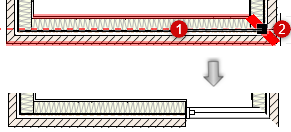
Drawing corner and span windows
Using Interactive Sizing Insertion mode, and with corner- and/or span-related parameters set by instance, you can quickly draw a corner or span window, in either a 3D or Top/Plan view. Place either click, for a corner window, or both clicks for a span window, beyond the end of the wall path.
To draw a corner or span window:
Begin to draw a window as described above, for the current view. The wall highlights as you move the cursor over it.
For either the first or second click, or both clicks for a span wall using Corner to Corner submode, extend the cursor past the end of the wall path. The end of the wall is highlighted to indicate a corner configuration, and in Top/Plan view, the square indicating the window edge is positioned at the wall end.
You can also draw a span wall using Center to Corner submode, as long as the first click is positioned so that the second click can encompass the ends of the wall paths on both corners.
When the wall is inserted, the Corner Window pane of the Window Settings dialog box automatically updates to indicate the selected window is a corner window or span window.