 Concept: Door and window assembly best practices
Difficulty level: Intermediate
Door and window assemblies are extremely flexible objects that can include a wide variety of parts and shapes. However, this flexibility also requires complexity. Following recommended best practices can help you get the results you're looking for.
Choose the best creation method
Because assemblies can take many different forms, and can be very simple or very complex objects, it's important to choose the most effective method for creating any given assembly.
In most cases, it's best to create an assembly from existing objects using the Create Door and Window Assembly context menu command. The assembly will be created using the current tool preferences.
For an assembly comprising a collection of typical doors and windows placed with the Door tool and Window tool, you should insert the doors and windows in a configuration as close as possible to the final assembly before using the Create Door and Window Assembly context command. When doors and windows abut, their frames must not overlap.
For assemblies that do not use unit-provided frames (such as storefronts), mullion width is determined by the adding the width of the adjacent frames plus any space between them. Set the frame widths accordingly.
For an assembly with a more unusual or creative shape, draw a closed 2D shape on the surface of the wall, and add parts to the assembly layout after the assembly is created.
To create a very complex assembly with many parts, begin by creating a much simpler assembly comprising a few basic doors and windows. Then edit the assembly layout to convert windows into other object types as needed, reshape/resize units, add or move mullions and other accessories, and so on.
To insert an assembly using an assembly style, use the Door and Window Assembly tool, and select the style on the Tool bar.

Frame options and assembly alignment
Each assembly that includes windows and/or doors can either use unit-provided frames (the frames provided by the individual window and door objects), or they can discard the individual frame information and have all units share the assembly's frame. Whether to use unit-provided frames is one of the most important decisions when creating an assembly, as it affects how multiple related settings behave within the assembly object. Consider this decision carefully at the beginning of the process. The Use unit-provided frames setting is on the Frame pane of the preferences dialog box.
Only doors and windows can use unit-provide frames. Panel, wall infill, and symbol units don't have their own frames.
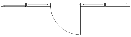
This assembly uses assembly-provided frames, and its Insertion Relative to setting is Center of Frame
To create an assembly of mulled units, use unit-provided frames. To create a storefront, don't use the unit-provided frames.
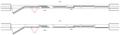
Mulled units with unit-provided frames (top) and a storefront with assembly-provided frames (bottom)
The assembly's Insert Relative to setting determines how the assembly overall aligns to the center or either face of its frame. The alignment of individual units within the assembly can be adjusted with other settings.
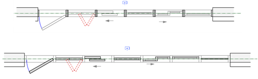
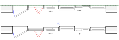
Assemblies with assembly-provided frames and an Insert Relative to setting of Interior Face of Frame (top) and Center of Frame (bottom)
The Unit Offset Reference, set for the assembly overall, tells the assembly how to locate all the units within the assembly relative to the frame center or either face of the frame. If the assembly was created from individual doors and windows using the Create Door and Window Assembly context menu command, all of the door and window individual Insert Relative to settings are overruled by the assembly's Unit Offset Reference. You can, however, give each unit in the assembly an individual offset, to ensure the proper location.
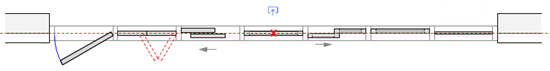
Assembly-provided frames with a Unit Offset Reference of Center of Assembly Frame (top) and Exterior Face of Assembly Frame (bottom). The assembly's Insert Relative to is set to Exterior Face of Frame; note how only the units move when the Unit Offset Reference changes.
For assemblies that use unit-provided frames, the Unit Offset Reference aligns all frames as set, regardless of their depths. For units with different frame depths, when the Insert Relative to setting is set to the exterior or interior face of the frame, units are aligned to the outermost or innermost edge of the frame with the greatest depth. Likewise, mullions in assemblies with unit-provided frames and a Location in Assembly of the exterior or interior face of the frame align to the outermost or innermost frame of all the frames in the assembly. Create offsets as needed for the correct alignment.
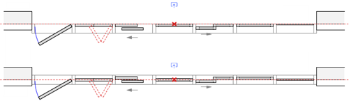
The assemblies shown use unit-provided frames, and each unit has a frame of a different depth. The Unit Offset Reference is set to Interior Face of Assembly Frame (top) and Exterior Face of Assembly Frame (bottom). All units align to the innermost/outermost face of the frame with the greatest depth, regardless of each unit's own frame depth. Adjust the Unit Offset for each unit as needed to align properly.
The Unit Offset settings for each unit in the assembly determine how each unit is placed relative to the offset reference, to accommodate the different alignment needs of different types of doors, windows, and so on. Positive offset values offset units toward the exterior side, and negative values offset toward the interior.
Of the four identical windows in this assembly, the one on the left has a Unit Offset of 4 cm (offset toward the exterior), and the one on the right has a Unit Offset of -4 cm (therefore offset toward the interior)
For mullions, the Location in Assembly and Offset in Assembly work similarly to the unit offset settings. Whichever reference point on the frame the Location in Assembly is set to, that part of the mullion aligns to the same part of the frame.
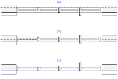
The mullions' Location in Assembly settings are Interior Face of Assembly Frame (top), Center of Assembly Frame (middle), and Exterior Face of Assembly Frame (bottom)
For assemblies with assembly-provided frames, such as storefronts:
The frame width is measured outward from the inside frame edge of each unit to keep the unit itself from changing size. For example, if a unit has a one-inch wide frame, and an assembly has a two-inch wide frame, the overall size of the assembly is increased by two inches - one inch in all directions.
Mullions between units are created where the frames exist, measuring out from the inside edge of each frame, and combine the width of the unit frames. For example, to create a two-inch mullion, abut two one-inch frames. In this way, the unit itself does not shrink to fit the allotted space.
Styled and unstyled assemblies and their parts
Door and window assemblies have various degrees of control, allowing you to choose which parts to control more tightly and which to leave more flexible to change with each instance.
An entire assembly can be set by style or by instance.
Within an assembly, the assembly layout can also by set by style or by instance. When the layout is set by style, the assembly's Overall Width and Overall Height are also set by style.
Within an assembly layout, the individual objects, such as doors, windows, mullions, and so on may also use a style. The by style/by instance settings of each object determine what can be edited within the layout.
Object size constraints, such as a door with the width set by style, may affecting editing behavior.
All objects within an assembly must use the interior side setting of the assembly, but individual doors and windows have their own handing.
In Top/Plan view, you may need to adjust the assembly cut plane to see the desired units and their handing controls, depending on their elevation in the assembly.
Reshape or resize the overall assembly
An unstyled assembly can be reshaped and resized. However, if the assembly layout or units within the assembly layout have sizes constrained by style or fixed widths/heights, those constraints limit how the assembly shape/size can be changed.
Use the Reshape tool to reshape the assembly in the design layer, just like any other polyline. When using the Reshape tool, only the units that touch the edge being edited are affected.
Resizing the assembly scales all unconstrained units in the assembly equally.
Edit the assembly layout
The parts that make up an assembly must be edited in the layout's object editing mode; click Edit Assembly Layout on the Object Info palette for a selected unstyled assembly, or in the Door and Window Assembly Style dialog box for an assembly style.
When editing the assembly layout, the Front view of the object always shows the exterior side of the assembly, and the other standard views are relative to that front view, regardless of the object's position in the design layer.
If you create a door and window assembly symbol, you should keep this orientation in mind. Model it with the exterior side facing the Front view within the symbol edit mode. The symbol's width adjusts as needed to fill the assembly's specified width. The symbol's depth remains constant, and its insertion point determines the symbol's location in relation to the depth of the assembly frame. A 2D/3D hybrid symbol works best.
To use a panel, wall infill, or symbol unit, create the assembly with a window or door in that position and then change it to the needed unit in the layout's object editing mode. Symbols are placed based on their insertion point rather than face alignment like the other unit types, so if you change another unit type to a symbol, check for proper alignment relative to the frame, mullions, and other units.
Some unit types have shape restrictions. For example, doors, wall infills, and symbols must be rectangular. If you edit the layout so that a unit's shape becomes non-rectangular, the unit is automatically replaced with a panel. The replacement panel used is determined by the Default Panel Style selection on the settings General pane, though you can change the panel in the layout's object editing mode. Panels can fit themselves to any shape between the frames and mullions, as can windows, though a window's configuration options are limited when it's non-rectangular.
A unit's Assembly Constraints settings apply when you resize or reshape an assembly in the design layer. You can always freely edit assemblies and units within them (depending on their style settings) in the layout's object editing mode.
Objects in an assembly that are locked by style, such as a window with dimensions set by style, maintain their style settings, regardless of how the layout is edited. Convert the individual object to unstyled if those settings need to change.
Door and window assembly tips
If you're creating an assembly from doors and windows, the frames of the individual doors and windows can't overlap; assembly creation may fail if they do.
For assemblies, wall closures are often excluded from the bottom by default, since many assemblies include doors; that setting can be adjusted in the plug-in object options.
Symbols within an assembly are located based on their insertion points rather than face alignment, as other unit types are. If you change another unit type to a symbol, check for proper alignment to the frame and other parts.
An assembly can span multiple walls, but is technically placed in only one. You must create an opening of the right size and shape in the other wall(s) for the assembly to look correct.
If you reshape an assembly using the Reshape tool, but see an undesired change in the width or height of some units, undo the reshape, and then enter the layout's object editing mode. Click the Edit Unit tool from the the Edit Assembly tool set, select the unit(s) with the size that should remain unchanged, and then click Fix width or Fix height in the Object Info palette, as needed.